5.3 UL Standards
192 SIEPYEUOQ2A01A AC Drive Q2A Technical Manual
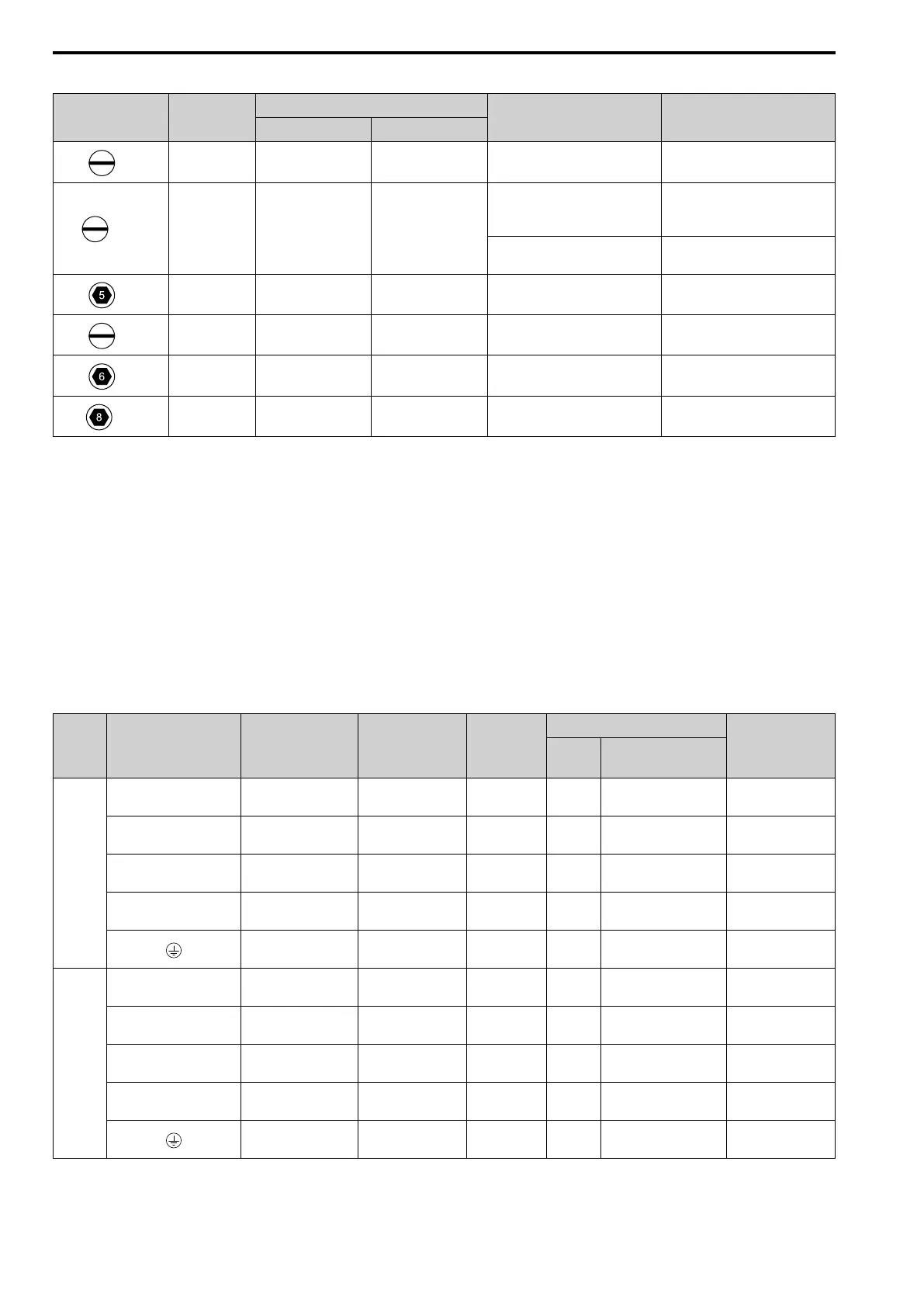
Table 5.7 Recommended Wiring Tools
Screw Adapter
Bit
Torque Driver Model
(Tightening Torque)
Torque Wrench
Model Manufacturer
M4
Bit SF-BIT-SL 1,0X4,0-70 PHOENIX CONTACT
TSD-M 3NM
(1.2 - 3 N∙m)
-
M5
*1
Bit SF-BIT-SL 1,2X6,5-70 PHOENIX CONTACT
Wire Gauge ≤ 25 mm
2
(AWG 10):
TSD-M 3NM
(1.2 - 3 N∙m)
Wire Gauge ≤ 25 mm
2
(AWG 10):
-
Wire Gauge ≥ 30 mm
2
(AWG 8):
-
Wire Gauge ≥ 30 mm
2
(AWG 8):
4.1 - 4.5 N∙m
*2 *3
M6
Bit SF-BIT-HEX 5-50 PHOENIX CONTACT - 5 - 9 N∙m
*2 *3
M6
Bit SF-BIT-SL 1,2X6,5-70 PHOENIX CONTACT - 3 - 3.5 N∙m
*2 *3
M8
Bit SF-BIT-HEX 6-50 PHOENIX CONTACT - 8 - 12 N∙m
*2 *3
M10
Bit SF-BIT-HEX 8-50 PHOENIX CONTACT - 12 - 14 N∙m
*2 *3
*1 When wiring drive models 4089 and smaller, select the correct tools for the wire gauge.
*2 Use 6.35 mm (0.25 in) bit socket holder.
*3 Use a torque wrench that can apply this torque measurement range.
■ Main Circuit Wire Gauges and Tightening Torques
Comply with local standards for correct wire gauges in the region where the drive is used.
WARNING! Electrical Shock Hazard. Only connect peripheral options, for example a DC reactor or braking resistor, to terminals
+1, +2, +3, -, B1, and B2. Failure to obey can cause death or serious injury.
Refer to Wire Gauges and Tightening Torques on page 75for general conditions
Drives from model 4208, use UL-approved closed-loop crimp terminals on the drive main circuit terminals. Use
the tools recommend by the terminal manufacturer and make sure that the terminals are correctly connected.
Select the correct wires for main circuit wiring.
Three-Phase 400 V Class
Model Terminals
Recommended
Gauge
AWG, kcmil
Applicable Gauge
(IP20 Applicable
Gauge
*1
)
AWG, kcmil
Wire
Stripping
Length
*2
mm
Terminal Screw
Tightening Torque
N∙m (lb∙in.)
Size Shape
4002
R/L1, S/L2, T/L3 14
14 - 6
(14 - 6)
10 M4 Slotted (-)
1.5 - 1.7
(13.5 - 15)
U/T1, V/T2, W/T3 14
14 - 6
(14 - 6)
10 M4 Slotted (-)
1.5 - 1.7
(13.5 - 15)
-, +1, +2 14
14 - 3
(14 - 3)
18 M5 Slotted (-)
2.3 - 2.5
(19.8 - 22)
*3
B1, B2 14
14 - 10
(14 - 10)
10 M4 Slotted (-)
1.5 - 1.7
(13.5 - 15)
12
14 - 8
(-)
- M4 Phillips/slotted combo
1.2 - 1.5
(10.6 - 13.3)
4004
R/L1, S/L2, T/L3 14
14 - 6
(14 - 6)
10 M4 Slotted (-)
1.5 - 1.7
(13.5 - 15)
U/T1, V/T2, W/T3 14
14 - 6
(14 - 6)
10 M4 Slotted (-)
1.5 - 1.7
(13.5 - 15)
-, +1, +2 14
14 - 3
(14 - 3)
18 M5 Slotted (-)
2.3 - 2.5
(19.8 - 22)
*3
B1, B2 14
14 - 10
(14 - 10)
10 M4 Slotted (-)
1.5 - 1.7
(13.5 - 15)
12
14 - 8
(-)
- M4 Phillips/slotted combo
1.2 - 1.5
(10.6 - 13.3)

 Loading...


