Parameter List
11
11.8 H: TERMINALS
SIEPYEUOQ2A01A AC Drive Q2A Technical Manual 437
No.
(Hex.)
Name Description
Default
(Range)
Ref.
H2-65
(1B4B)
Expert
3NO-3CM Dly Time
Sets the minimum on time used to output the logical calculation results from terminal
3NO-3CM.
0.1 s
(0.0 - 25.0 s)
696
H2-66
(1B4C)
Expert
4NO-4CM 2nd Function
Selects the second function for terminal 4NO-4CM. The logical calculation results of
the terminals assigned to functions by H2-03 [4NO-4CM Funct Selection] is output.
0
(0 - A7)
696
H2-67
(1B4D)
Expert
4NO-4CM Logic
Operation
Sets the logical operation for the functions set in H2-03 [4NO-4CM Funct Selection]
and H2-66 [4NO-4CM 2nd Function].
1
(1 - 9)
696
H2-68
(1B4E)
Expert
4NO-4CM Dly Time
Sets the minimum on time used to output the logical calculation results from terminal
4NO-4CM.
0.1 s
(0.0 - 25.0 s)
697
■ H2-xx: MFDO Function Selections
Setting Function Description Ref.
0 Through Mode
Use this setting for unused terminals or to use terminals in through mode. Also use this setting as the PLC contact
output via Modbus or the communication option. This signal does not function if signals from the PLC are not
configured.
697
1 Drive Ready
The terminal activates when the drive is ready and running.
697
2 Drive Enable
This terminal activates when the H1-xx = 1A [Drive Enable] terminal activates.
697
3 Fault
The terminal activates when the drive detects a fault.
Note:
The terminal will not turn on for CPF00 and CPF01 [Control Circuit Error] faults.
697
4 Alarm
The terminal turns on when the drive detects a minor fault.
697
5 @Run
The terminal activates when the Run command is input and when the drive is making voltage.
ON : Drive is running
OFF : Drive is stopping
697
6 @Reverse
The terminal activates when the motor operates in the reverse direction.
ON : The motor is operating in the reverse direction.
OFF : The motor is operating in the forward direction or the motor stopped.
698
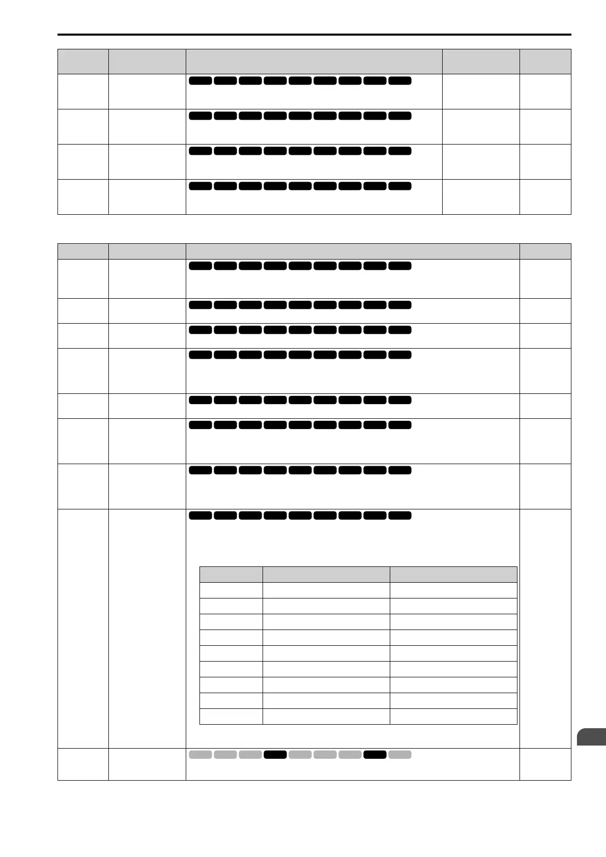
7 Zero Speed
The terminal activates when the output frequency is less than the value of E1-09 [Min Output Frequency] or b2-01
[ZSpd/DCI Threshold].
Note:
A1-02 [Control Method] selects which parameter is the reference.
A1-02 Setting Control Method Parameter Used as the Reference
0 V/f Control E1-09
1 PG V/f Control E1-09
2 OLVector b2-01
3 CLVector E1-09
4 Adv OLVector E1-09
5 PM OLVector E1-09
6 PM AOLVector E1-09
7 PM CLVector b2-01
8 EZ Vector E1-09
ON : Output frequency < value of E1-09 or b2-01.
OFF : Output frequency ≥ value of E1-09 or b2-01.
698
8 ZeroServo ok
The terminal activates when positioning in the range set with b9-02 [Zero Servo Width for Completion] completes
after sending the Zero-Servo command.
699
 Loading...


