Parameter List
11
11.16 A1-02 [Control Method] Dependent Parameters
SIEPYEUOQ2A01A AC Drive Q2A Technical Manual 485
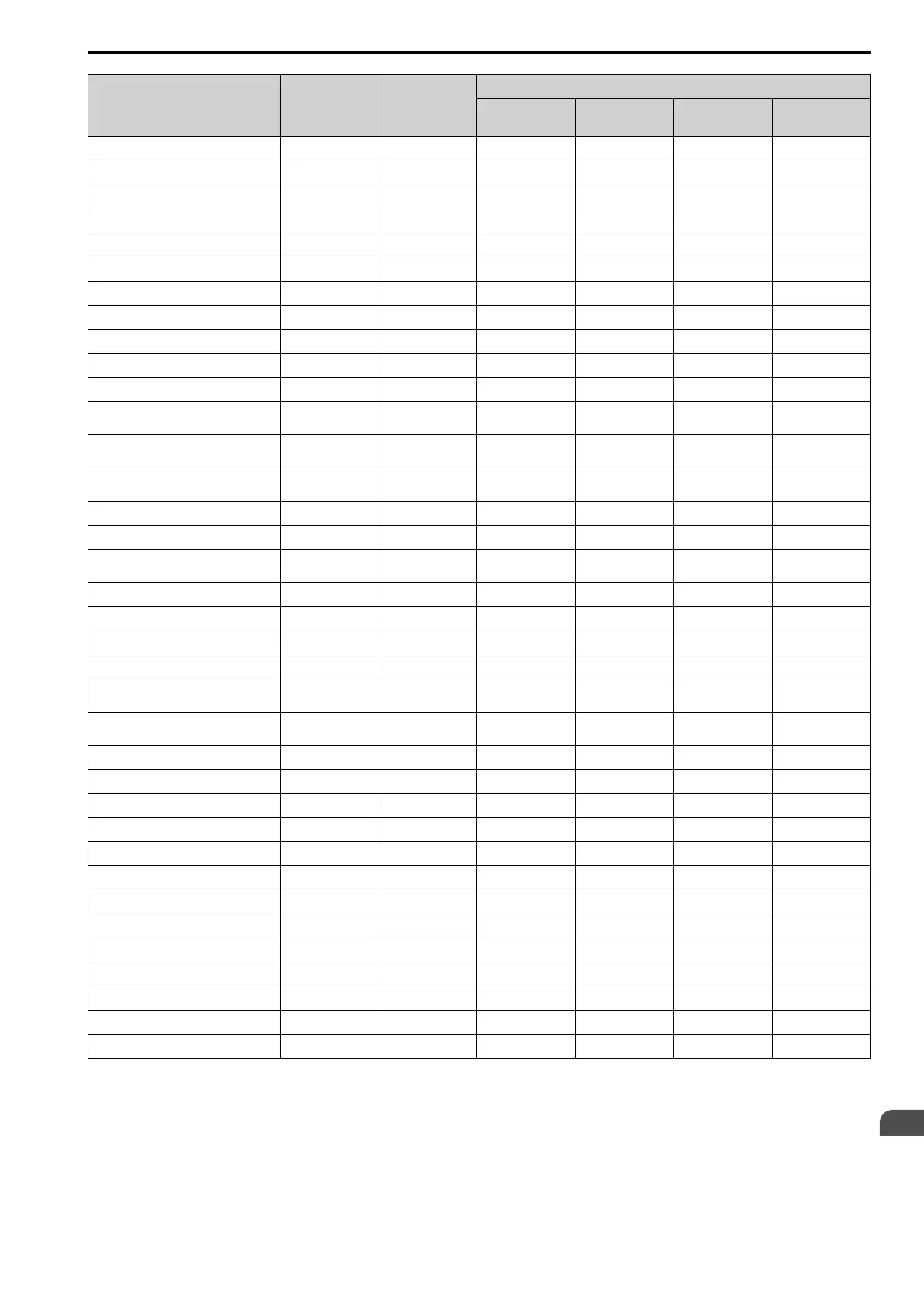
No. Setting Range Unit
Control Method
PM OLVector
(5)
PM AOLVector
(6)
PM CLVector
(7)
EZ Vector
(8)
C5-02 ASR ITime 1 0.000 - 60.000 0.001 s 0.500 0.500 0.500 0.500
C5-03 ASR PGain 2 0.00 - 300.00 0.01 - 10.00 20.00 10.00
C5-04 ASR ITime 2 0.000 - 10.000 0.001 s - 0.500 0.500 0.500
C5-06 ASR Delay Time 0.000 - 0.500 0.001 s - 0.016 0.004 0.004
C5-07 ASR Gain Switch Frequency 0.0 - 400.0
*1
0.1 0.0 Hz 0.0 % 0.0 % 0.0 %
C6-02 Carrier Frequency Selection 1 - F 1 2 2 2 2
d3-01 Jump Frequency 1 0.0 - 400.0
*1
0.1 0.0 Hz 0.0 % 0.0 % 0.0 %
d3-02 Jump Frequency 2 0.0 - 400.0
*1
0.1 0.0 Hz 0.0 % 0.0 % 0.0 %
d3-03 Jump Frequency 3 0.0 - 400.0
*1
0.1 0.0 Hz 0.0 % 0.0 % 0.0 %
d3-04 Jump Frequency Width 0.0 - 20.0
*2
0.1 1.0 Hz 1.0 % 1.0 % 1.0 %
d5-02 Torque Ref Delay Time 0 - 1000 1 ms - - 0 -
E1-04 Max Output Frequency 40.0 - 400.0
*3
0.1 Hz
Determined by E5-
01
Determined by E5-
01
Determined by E5-
01
-
E1-05 Max Output Voltage 0.0 - 255.0
*4
0.1 V
Determined by E5-
01
Determined by E5-
01
Determined by E5-
01
-
E1-06 Base Frequency 0.0 - 400.0 0.1 Hz
Determined by E5-
01
Determined by E5-
01
Determined by E5-
01
-
E1-07 Mid A Frequency 0.0 - 400.0 0.1 Hz - - - -
E1-08 Mid AVoltage 0.0 - 255.0
*4
0.1 V - - - -
E1-09 Min Output Frequency 0.0 - 400.0 0.1 Hz
Determined by E5-
01
Determined by E5-
01
0.0 -
E1-10 Min Output Voltage 0.0 - 255.0
*4
0.1 V - - - -
F1-01 Enc1 Pulse Count (PPR) 0 - 60000 1 ppr 1024 1024 1024 600
F1-05 Enc1 Rotat Selection 0 - 1 1 1 1 1 0
F1-09 Overspeed Delay Time 0.0 - 2.0 0.1 s - - 0.0 -
H4-20 An.Pwr Mon 100% Level 0.00 - 650.00 0.01
Determined by E5-
01
Determined by E5-
01
Determined by E5-
01
Determined by E9-
07
L1-01 Motor Cool Type for OL1 Calc 0 - 4 1 4 4 5
Determined by E9-
01
L3-05 StallP@RUN Enable 0 - 3 1 1 - - 3
L3-20 DCBus VoltAdj Gain 0.00 - 5.00 0.01 0.65 0.65 0.65 0.65
L3-21 OVSup Acc/Dec Gain 0.10 - 10.00 0.01 1.00 1.00 1.00 1.00
L3-36 VibSup Gain@Accel 0.0 - 100.0 0.1 - - - -
L4-01 SpAgree Det.Level 0.0 - 400.0
*1
0.1 0.0 Hz 0.0 % 0.0 % 0.0 %
L4-02 SpAgree Det.Width 0.0 - 20.0
*2
0.1 2.0 Hz 4.0% 4.0% 4.0%
L4-03 SpAgree Det.Level(+/-) -400.0 - +400.0
*5
0.1 0.0 Hz 0.0 % 0.0 % 0.0 %
L4-04 SpAgree Det.Width(+/-) 0.0 - 20.0
*2
0.1 2.0 Hz 4.0% 4.0% 4.0%
L8-38 Carrier Reduction Mode 0 - 2 1 0 0 0 0
L8-40 Carrier Red Off-Delay Time 0.00 - 2.00 0.01 s 0.00 0.00 0.00 0.00
n1-15 PWM VOffset Calibration 0 - 2 1 1 1 1 1
o1-03 FrqDisplay Unit Selection 0 - 3 1 0 1 1 1
o1-04 V/f Pattern Unit for Display 0 - 1 1 - 1 1 -
*1 The setting range is 0.0 to 100.0 when A1-02 = 6 or 7 [Control Method = PM AOLVector or PM CLVector].
*2 The setting range is 0.0 to 40.0 when A1-02 = 6 or 7 [Control Method = PM AOLVector or PM CLVector].
*3 The default setting varies depending on the setting of ND/HD Duty Selection.
*4 This is the value for 200 V class drives. Double the value for 400 V class drives.
*5 The setting range is -100.0 to +100.0 when A1-02 = 6 or 7 [Control Method = PM AOLVector or PM CLVector].

 Loading...


