12.6 F: OPTIONS
644 SIEPYEUOQ2A01A AC Drive Q2A Technical Manual
When you install a DO-A3 to the drive, you can output isolated digital signals to monitor the drive operation
status.
• 6 points of photocoupler output (48 V, 50 mA or less)
• 2 points of relay contact output (250 Vac, 30 Vdc: 1 A or less)
Refer to the DO-A3 option manual for more information about how to install, wire, and set the DO-A3 card.
■ Use Parameters to Select Output Modes
Use parameter F5-09 [DO-A3 Output Mode Selection] to set signal output from the DO-A3 card.
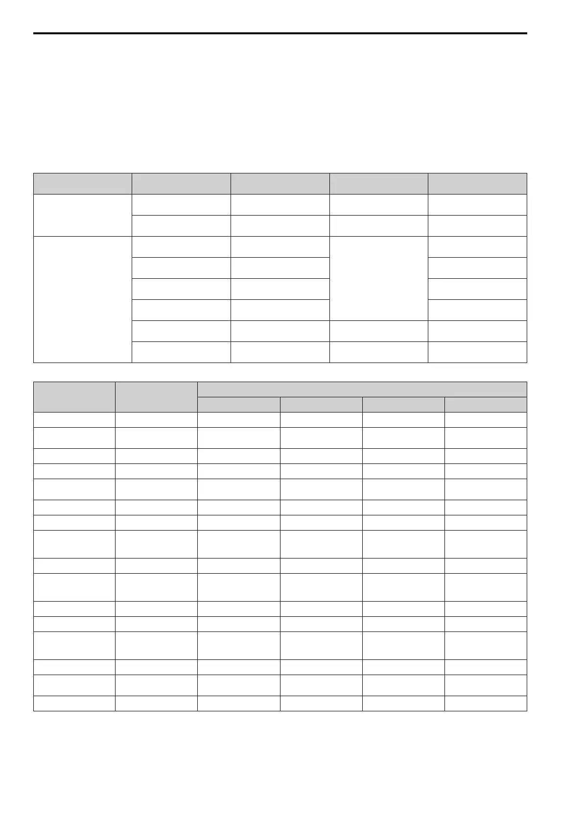
Table 12.32 Details of F5-09 and the DO-A3 Terminal Output
DO-A3 Terminal Block DO-A3 Terminal Name
F5-09 = 0 [8 CH Individual]
(Default)
F5-09 = 1 [Bin Code Output]
F5-09 = 2 [8 CH Sel (F5-01 to
F5-08)]
TB1 M1-M2 Zero speed detection in progress During run Depending on the setting of F5-07
[Term.M1-M2 Function Select]
M3-M4 During speed agreement Minor fault (excluding bb
[Baseblock])
Depending on the setting of F5-08
[Term.M3-M4 Function Select]
TB2 P1-PC oC [Overcurrent], GF [Ground
Fault]
Coded output
Note:
Refer to Table 12.33 for
details.
Depending on the setting of F5-01
[Term.P1-PC Function Select]
P2-PC ov [Overvoltage] Depending on the setting of F5-02
[Term.P2-PC Function Select]
P3-PC oL2 [Drive Overload] or oH2
[Heatsink Overheat]
Depending on the setting of F5-03
[Term.P3-PC Function Select]
P4-PC Not used Depending on the setting of F5-04
[Term.P4-PC Function Select]
P5-PC oS [Overspeed] Zero speed detection in progress Depending on the setting of F5-05
[Term.P5-PC Function Select]
P6-PC oH, oH1 [Heatsink Overheat] or
oL1 [Motor Overload]
During speed agreement Depending on the setting of F5-06
[Term.P6-PC Function Select]
Table 12.33 Binary Output [F5-09 = 1]
Coded Output (Binary) Description
DO-A3 Terminal Block TB2
Terminal P1-PC Terminal P2-PC Terminal P3-PC Terminal P4-PC
0 No fault 0 0 0 0
1 oC [Overcurrent], GF
[Ground Fault]
1 0 0 0
2 ov [Overvoltage] 0 1 0 0
3 oL2 [Drive Overloaded] 1 1 0 0
4 oH, oH1 [Heatsink
Overheat]
0 0 1 0
5 oS [Overspeed] 1 0 1 0
6 Not used 0 1 1 0
7 rr [Dynamic Braking
Transistor Fault], rH
[Braking Resistor Overheat]
1 1 1 0
8 External fault [EF1 to EF8] 0 0 0 1
9 CPFxx, oFAxx, oFbxx,
oFCxx [Drive Hardware
Fault]
*1
1 0 0 1
A oL1 [Motor Overload] 0 1 0 1
B Not used 1 1 0 1
C Uv1, Uv2 [Undervoltage],
Uv3 [Soft Charge
Answerback Fault]
0 0 1 1
D dEv [Speed Deviation] 1 0 1 1
E PGo [Encoder (PG)
Feedback Loss]
0 1 1 1
F Not used 1 1 1 1
*1 The “xx” characters are different for different faults.

 Loading...


