12.7 H: TERMINALS
720 SIEPYEUOQ2A01A AC Drive Q2A Technical Manual
If you use drives in applications where the vertical axis can fall, make sure that you know these items:
• Correctly configure drives and motors.
• Correctly set parameters.
• You can change parameter values after you do Auto-Tuning.
• Use a system that will not let the vertical axis fall if the drive fails.
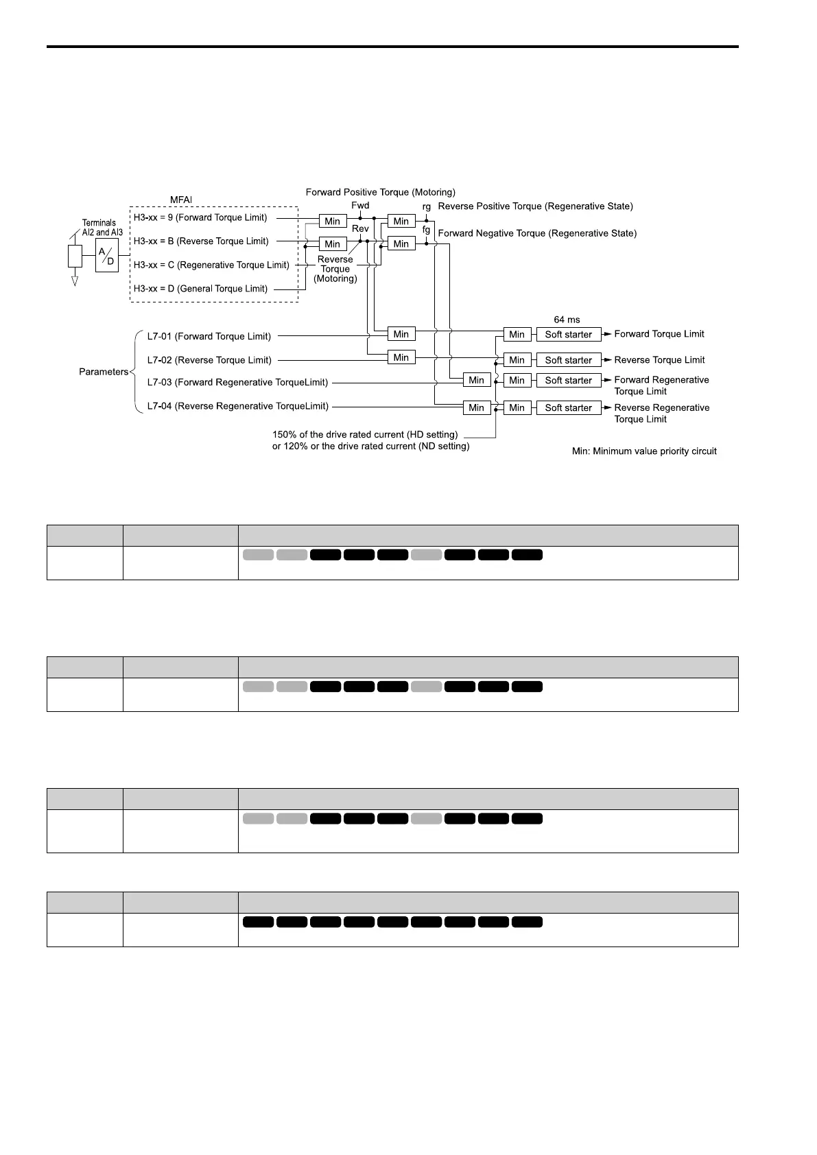
Figure 12.103 shows the relation between torque limits from parameters and torque limits from analog input.
Figure 12.103 Torque Limits from Parameters and Analog Inputs
■ B: Rev Trq Lim
Setting Function Description
B Rev Trq Lim
Enters the load torque limit if the motor rated torque is 100%.
Note:
When you use L7-01 to L7-04 and analog inputs to set torque limits for the same quadrant, it will enable the lower torque limit.
■ C: RegenTrqLim
Setting Function Description
C RegenTrqLim
Enters the regenerative torque limit if the motor rated torque is 100%.
Note:
When you use L7-01 to L7-04 and analog inputs to set torque limits for the same quadrant, it will enable the lower torque limit.
■ D: GenerTrqLim
Setting Function Description
D GenerTrqLim
Enters the torque limit that is the same for all quadrants for forward, reverse, and regenerative operation if the motor rated
torque is 100%.
■ E: OvUntrq Level
Setting Function Description
E OvUntrq Level
Enters a signal to adjust the overtorque/undertorque detection level.
When A1-02 = 0, 1, 5 [Control Method = V/f Control, PG V/f Control, PM OLVector], the drive rated current is
100%. When A1-02 = 2, 3, 4, 6, 7, 8 [OLVector, CLVector, Adv OLVector, PM AOLVector, PM CLVector, EZ
Vector], the motor rated current is 100%.
Note:
Use this function with L6-01 [Trq Det1 Select]. This parameter functions as an alternative to L6-02 [Trq Det1 Level].

 Loading...


