3.3 Main Circuit Wiring
76 SIEPYEUOQ2A01A AC Drive Q2A Technical Manual
■ Cable Length Between Drive and Motor
When the wiring between the drive and the motor is too long, voltage drop along the motor cable can decrease
motor torque, usually at low frequency output. If you connect motors in parallel with long motor cable, this is also
a problem. Drive output current increases when the leakage current from the cable increases. An increase in
leakage current can cause overcurrent and decrease the precision of the current detection.
Use the values in Table 3.2 to adjust the drive carrier frequency. When the system configuration makes the motor
wiring distance more than 100 m (328 ft), do not use metal conduits or use isolated cables for each phase to
decrease stray capacitance.
Table 3.2 Carrier Frequency against Cable Length Between Drive and Motor
Cable Length Between Drive and
Motor
Up to 50 m (164 ft.) Up to 100 m (328 ft.) More than 100 m (328 ft.)
Carrier Frequency 15 kHz or less 5 kHz or less 2 kHz or less
Note:
• To set the carrier frequency in a drive that is operating more than one motor, calculate the cable length as the total distance of wiring to
all connected motors.
• In A1-02 = 5 or 6 [Control Method = PM OLVector or PM AOLVector], the maximum cable length is 100 m (328 ft.).
• When you connect to a PM motor, it can be necessary to adjust the overcurrent detection. Refer to L8-27 OverCurr Det Gain on page
777 for more information.
■ Ground Wiring
Follow the precautions to wire the ground for one drive or a series of drives.
WARNING! Electrical Shock Hazard. Make sure that the protective ground wire complies with technical standards and local
safety regulations. The leakage current of the drive will be more than 3.5 mA. The IEC/EN 61800-5-1:2007 standard specifies
that you must wire the power supply to automatically turn off when the protective ground wire disconnects. You can also
connect a protective ground wire that has a minimum cross-sectional area of 10 mm
2
(copper wire) or 16 mm
2
(aluminum wire).
Failure to obey these standards can cause death or serious injury.
WARNING! Electrical Shock Hazard. Ground the neutral point on the power supply to comply with the EMC Directive before
turning on the EMC filter or if there is high resistance grounding. If the EMC filter is switched ON without the neutral point being
grounded or if there is high resistance grounding, it can cause death or serious injury.
WARNING! Electrical Shock Hazard. Use a ground wire that complies with technical standards on electrical equipment and use
the minimum length of ground wire. Incorrect equipment grounding can cause serious injury or death from dangerous electrical
potentials on the equipment chassis.
WARNING! Electrical Shock Hazard.
Correctly ground the ground terminals. Obey federal and local electrical wiring codes for correct grounding methods.
• 400 V class: ground to 10 Ω or less
Failure to obey can cause death or serious injury from contacting ungrounded electrical equipment.
NOTICE: Do not share the ground wire with other devices, for example welding machines or large-current electrical equipment.
Incorrect equipment grounding can cause drive or equipment malfunction from electrical interference.
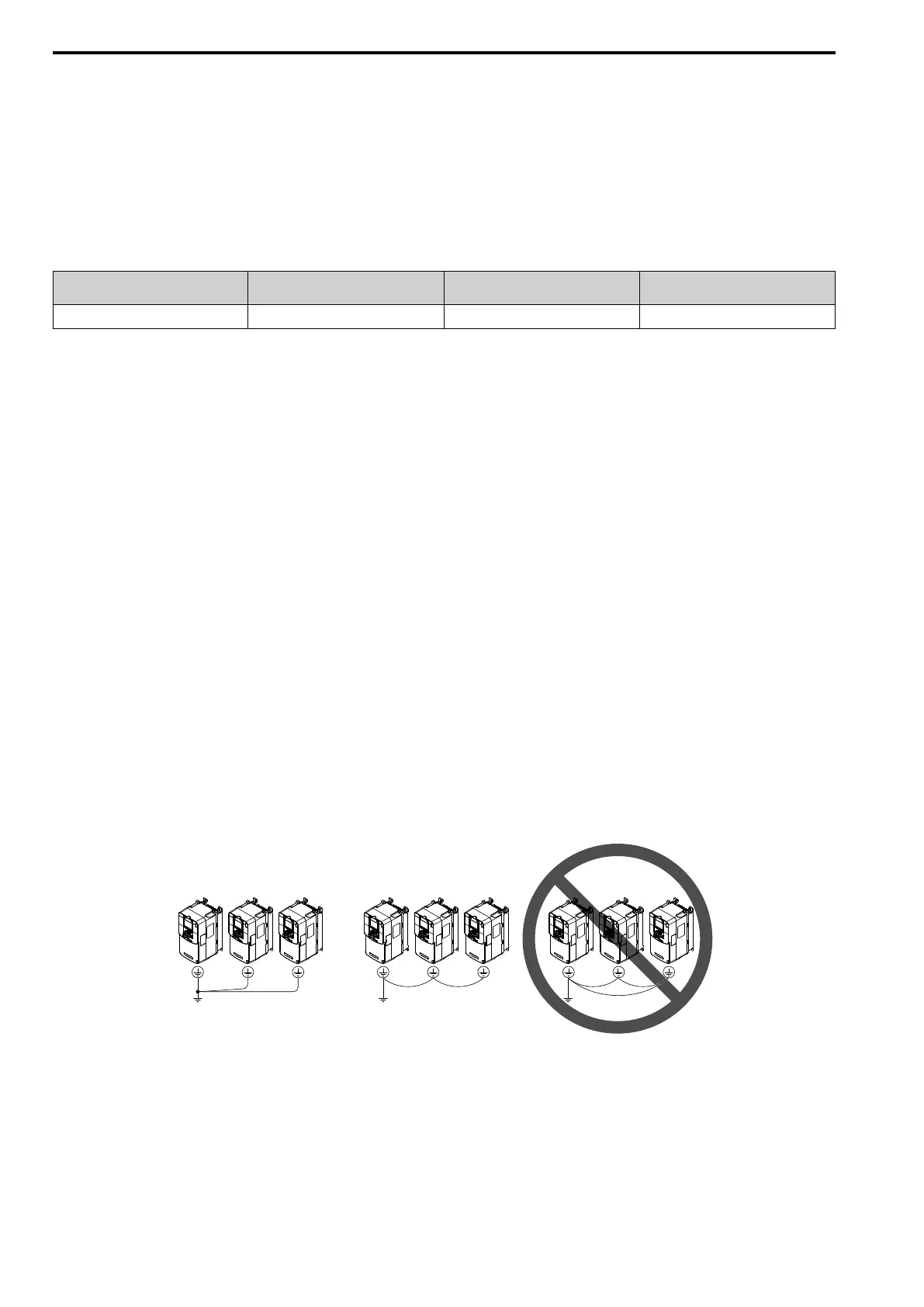
NOTICE: To use more than one drive, obey the instructions to ground all drives. Incorrect equipment grounding can cause
incorrect operation of drives and equipment.
Do not loop the grounding wire when connecting more than one drive.
Figure 3.14 Wiring More than One Drive
■ Wiring the Main Circuit Terminal Block
WARNING! Electrical Shock Hazard. De-energize the drive and correctly ground the terminal board before you wire the main
circuit terminals. Failure to obey can cause death or serious injury.

 Loading...


