Electrical Installation
3
3.4 Main Circuit Terminal Block Wiring
SIEPYEUOQ2A01A AC Drive Q2A Technical Manual 81
• Remove the correct section of the wiring cover to make wiring easier.
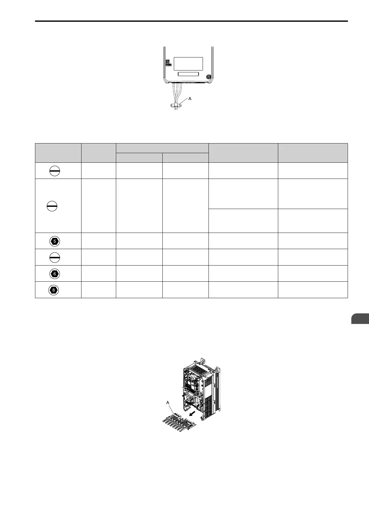
• Do not let strain on the wiring cause damage. Use a strain relief near the wiring to release the tension.
A - Strain relief
Figure 3.21 Strain Relief Example
Table 3.3 Recommended Wiring Tools
Screw Adapter
Bit
Torque Driver Model
(Tightening Torque)
Torque Wrench
Model Manufacturer
M4
Bit SF-BIT-SL 1,0X4,0-70 PHOENIX CONTACT
TSD-M 3NM
(1.2 - 3 N∙m)
-
M5
*1
Bit SF-BIT-SL 1,2X6,5-70 PHOENIX CONTACT
Wire Gauge
≤ 25 mm
2
(AWG 10):
TSD-M 3NM
(1.2 - 3 N∙m)
Wire Gauge
≤ 25 mm
2
(AWG 10):
-
Wire Gauge
≥ 30 mm
2
(AWG 8):
-
Wire Gauge
≥ 30 mm
2
(AWG 8):
4.1 - 4.5 N∙m
*2 *3
M6
Bit SF-BIT-HEX 5-50 PHOENIX CONTACT - 5 - 9 N∙m
*2 *3
M6
Bit SF-BIT-SL 1,2X6,5-70 PHOENIX CONTACT - 3 - 3.5 N∙m
*2 *3
M8
Bit SF-BIT-HEX 6-50 PHOENIX CONTACT - 8 - 12 N∙m
*2 *3
M10
Bit SF-BIT-HEX 8-50 PHOENIX CONTACT - 12 - 14 N∙m
*2 *3
*1 When wiring drive models 4089 and smaller, select the correct tools for the wire gauge.
*2 Use 6.35 mm (0.25 in) bit socket holder.
*3 Use a torque wrench that can apply this torque measurement range.
■ Main Circuit Terminal Block Wiring Procedure
The keypad and front cover must be removed before wiring the main circuit terminal block.
1. Pull the wiring cover forward to remove it from the drive.
A - Wiring cover
Figure 3.22 Remove the Wiring Cover

 Loading...


