5-20
CHAPTER 5 Periodic Inspection
11) Remove the Y-axis harmonic drive from the top of the X-axis arm.
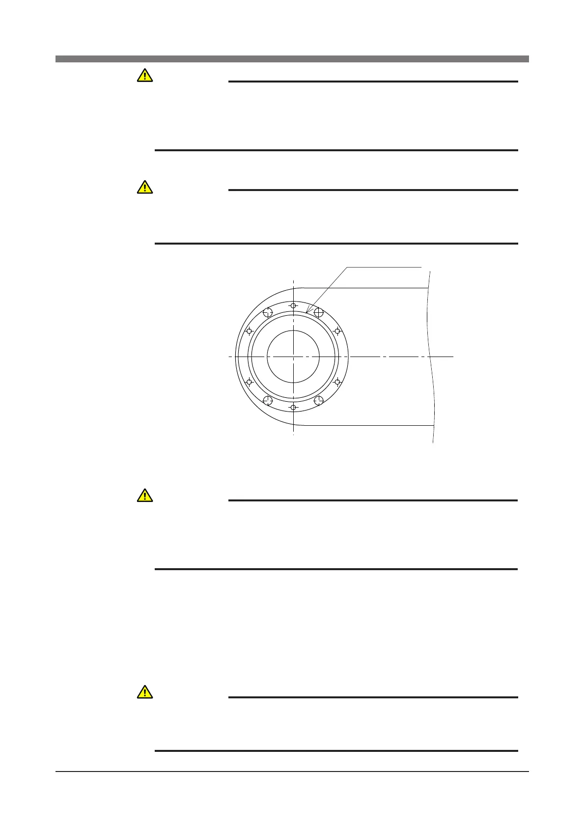
O-ring
(S63 : KN3-M2519-000)
Fig. 5-9
12) Remove the four bolts temporarily tightened to the new harmonic drive.
13) Fit a new O-ring coated with harmonic grease into the O-ring groove on the
X-axis arm. (See Fig. 5-9.)
14) Place the new harmonic drive on the X-axis arm, and secure it with the
bolts (M3×40L, 6 pieces). Apply small amounts of "Screw Lock" to the
bolts and tighten uniformly them to secure the harmonic drive from the
backside. (See Fig. 5-8.)
CAUTION
THE DOG RING IS USED FOR REASSEMBLY. STORE IT WHERE THE
WORK WILL NOT BE DISTURBED.
THE DOG RING IS PROVIDED WITH THE SETSCREWS. BE CAREFUL TO
AVOID LOSING THEM.
CAUTION
AN O-RING IS FITTED TO THE X-AXIS HARMONIC DRIVE, SO BE
CAREFUL NOT TO LET IT DROP INTO THE PERIPHERAL UNIT. (SEE FIG.
5-9.)
CAUTION
REMOVE ONLY THE FOUR BOLTS SHOWN IN FIG. 5-10 AT THIS POINT.
NEVER REMOVE THE BOLTS ON THE OPPOSITE SIDE. IF THEY ARE
REMOVED, THE HARMONIC DRIVE AXIS MAY DEVIATE FROM THE
CENTER CAUSING TROUBLE.
CAUTION
DO NOT ALLOW THE O-RING TO GET CAUGHT OUT OF THE GROOVE
DURING REASSEMBLY. A PROBLEM WILL OCCUR IF THE ROBOT IS
OPERATED WITH THE O-RING LEFT CAUGHT OUT OF THE GROOVE.
 Loading...


