5-21
CHAPTER 5 Periodic Inspection
15) Fasten the dog ring on the Harmonic drive.
16) Fit an O-ring (supplied with the harmonic drive) coated with harmonic
grease into the O-ring groove on the new harmonic drive
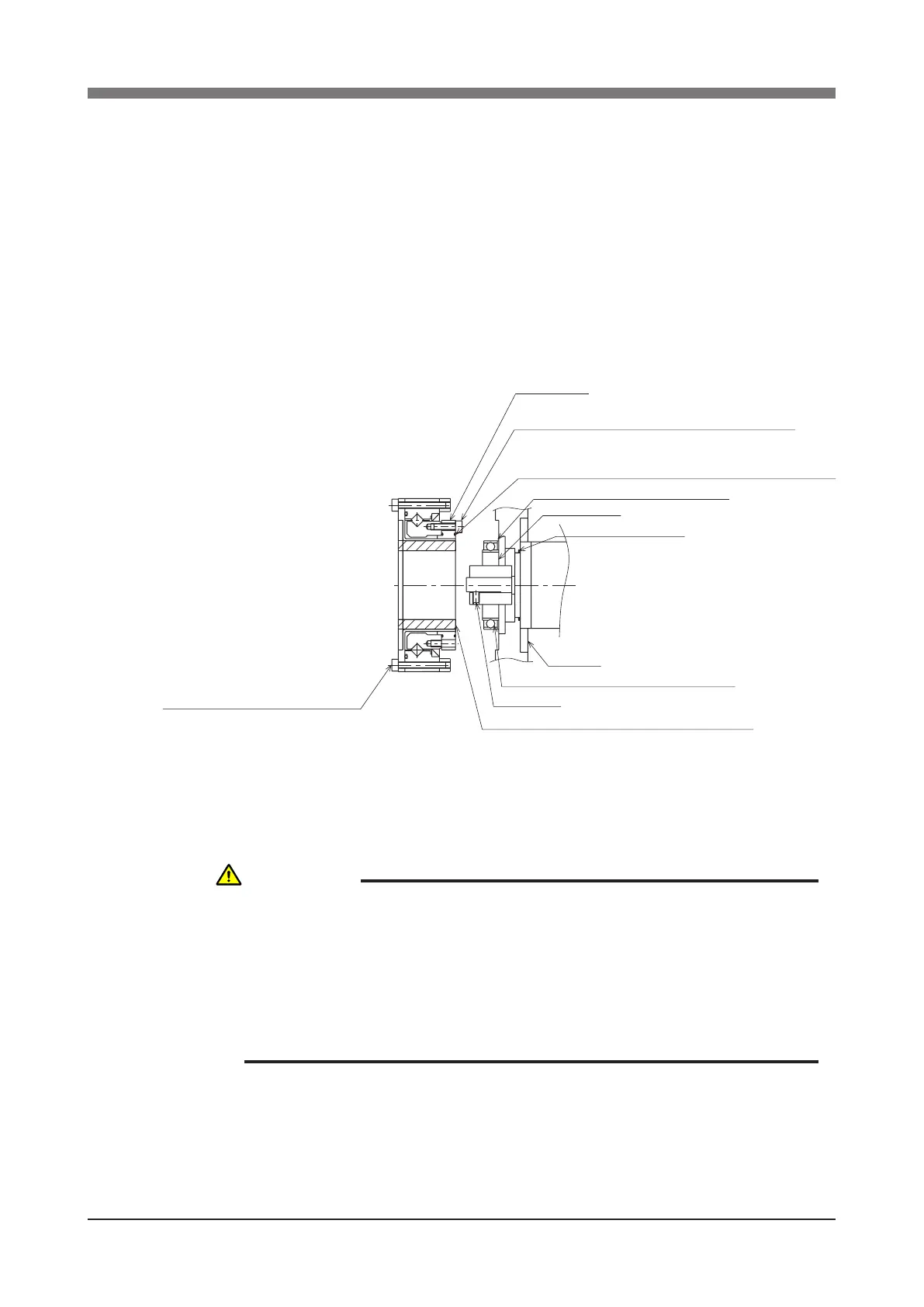
17) Apply harmonic grease to the new wave generator and exspline.
See Fig. 5-10 for applying grease properly.
18) Fit the wave generator onto the motor shaft and fully insert it against the
motor. Then, apply small amounts of "Screw Lock" to the M3 set screw (2
piece) you removed earlier and tighten it to secure the wave generator. (See
Fig. 5-10.)
Fit O-ring (supplied) into this groove
Harmonic drive will be damaged if O-ring is caught out of groove.
O-ring : KN3-M257L-000
Never remove these temporarily tightened bolts.
The axis will otherwise deviate from center.
Apply grease to sufficiently fill in the ball space.
Apply grease to entire oldham coupling.
Apply grease to the thickness equal to the ball diameter.
Circular spline
M3 set screw
Wave generator
O-ring : KN3-M257K-000
Y-axis arm
Remove the temporarily tightened bolts when assembling
Keep the circular spline from coming off when assembling
Fig. 5-10
19) Secure the Y-axis arm to the harmonic drive with the bolts (M3×20L, 8
pieces) you removed earlier. Apply small amounts of "Screw Lock" to the
bolts and tighten them uniformly to secure the Y-axis arm. (See Fig. 5-7.)
CAUTION
DO NOT ALLOW THE O-RING TO GET CAUGHT OUT OF THE GROOVE
DURING REASSEMBLY. A PROBLEM WILL OCCUR IF THE ROBOT IS
OPERATED WITH THE O-RING LEFT CAUGHT OUT OF THE GROOVE.
WHEN REASSEMBLING THE HARMONIC DRIVE, BE CAREFUL TO KEEP
THE CIRCULAR SPLINE FROM COMING OFF. IF IT COMES OFF, THE
HARMONIC DRIVE AXIS WILL DEVIATE FROM THE CENTER CAUSING
TROUBLE.
 Loading...


