5-31
CHAPTER 5 Periodic Inspection
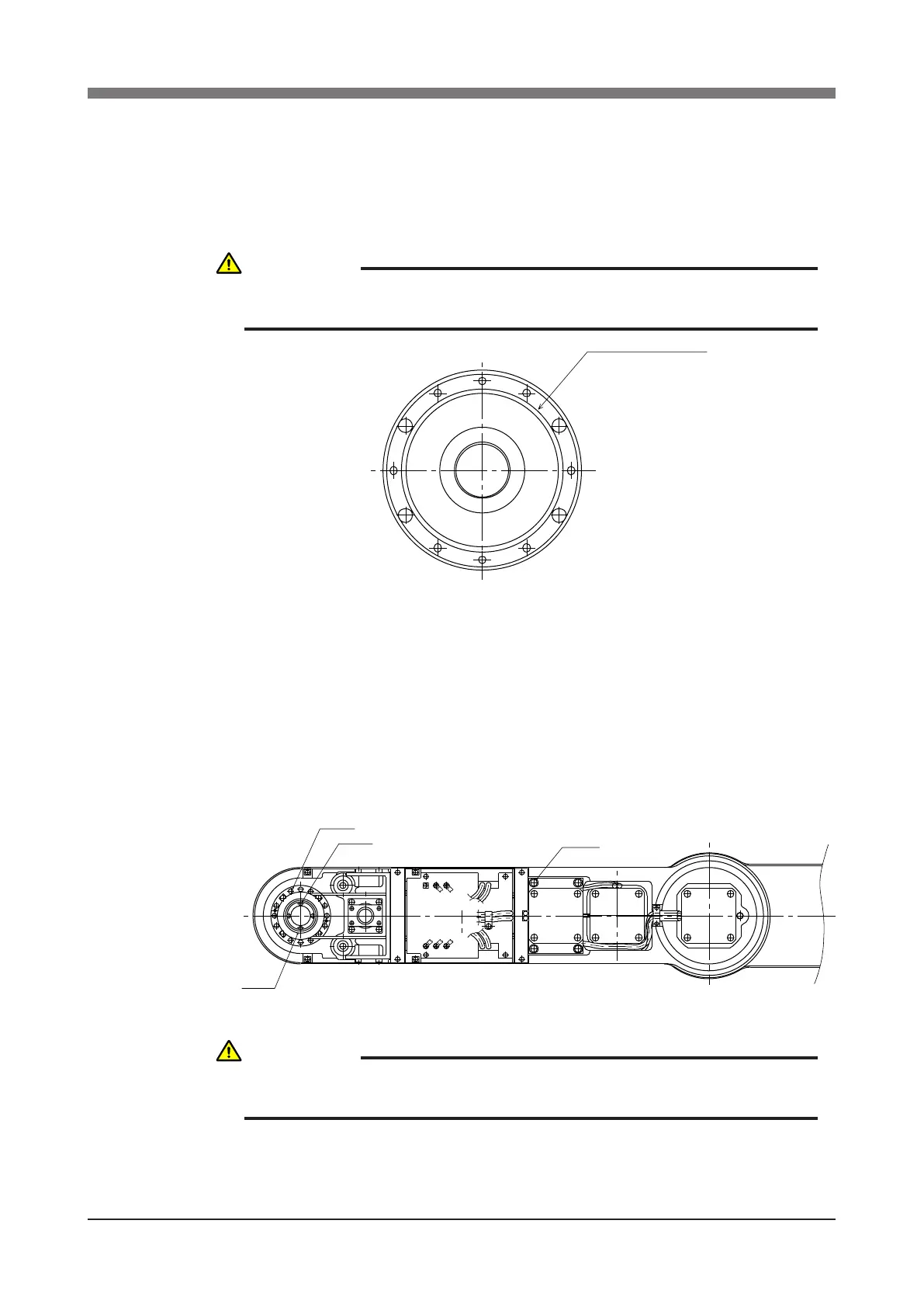
9) Remove the bolts (M4×14L, 2 pieces) on the underside of the Y-axis arm
and remove the R-axis dog ring from the fastening plate.
10) Remove the bolts (M4×30L, 8 pieces) on the underside of the Y-axis arm
and remove the plate fastening the spline and the harmonic drive. (See Fig.
5-18.)
Fig. 5-21
11) Remove the bolts (M6×20L, 4 pieces) securing the R-axis motor plate at
the top of the Y-axis arm. (See Fig. 5-22.)
12) Loosen the pulley bolts (M3×30L, 4 pieces) and remove the pulley fastened
to the wave generator. (See Fig. 5-22.)
13) Remove the harmonic drive installation bolts (M4×45L, 12 pieces) and pull
out the harmonic drive from the bottom of the Y-axis arm. (See Fig. 5-22.)
Fig. 5-22
14) Pull out the wave generator from the bottom of the Y-axis arm.
CAUTION
AN O-RING IS FITTED TO THE FASTENING PLATE, SO BE CAREFUL
NOT TO LET IT DROP INTO THE PERIPHERAL UNIT. (SEE FIG. 5-21.)
CAUTION
AN O-RING IS FITTED TO THE HARMONIC DRIVE, SO BE CAREFUL
NOT TO LET IT DROP INTO THE PERIPHERAL UNIT.
 Loading...


