5-33
CHAPTER 5 Periodic Inspection
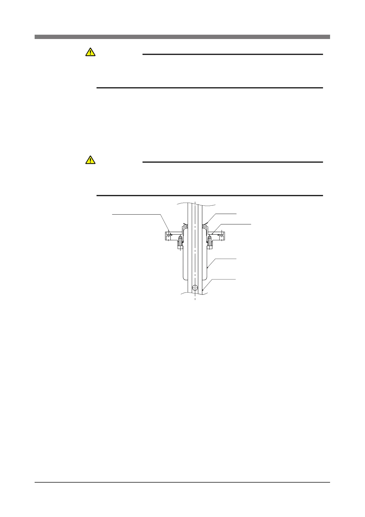
21) Fit a new O-ring into the O-ring groove on the fastening plate and also
replace the edge seal with new one. Then, secure the fastening plate to
the harmonic drive with the bolts (M4×30L, 8 pieces) coated with small
amounts of "Screw Lock". (See Figs. 5-18 and 5-24.)
At this point, be careful to keep the spline shaft from coming off the spline
nut.
O-ring : KN4-M2143-000
Edge seal
Fastening plate
Spline nut
Spline shaft
Fig. 5-24
22) Secure the dog ring to the fastening plate with the bolts (M4×14L, 2 piec-
es).
23) Insert the spline shaft into the holder, t the bearing onto the spline and
tighten the U-nut to secure the bearing. (Utilize the φ10 through-hole when
tightening the U-nut like you did to loosen it.) (See Fig. 5-20.)
24) Put the bearing into the holder and tighten the bolts (M6×20L, 4 pieces) to
secure the bearing mount plate to the holder (See Fig. 5-19.)
25) Install the spline support shafts (2 pieces) to the fastening plate, apply a
small amount of "Screw Lock" to the bolts (M5×20L, 4 pieces) and tighten.
(See Fig. 5-18.)
26) Attach the Y-axis arm front cover.
27) Go outside the safeguard enclosure.
28) Check that no one is inside the safeguard enclosure, and then turn on the
controller.
CAUTION
WHEN SECURING THE TIMING BELT, THE BELT TENSION MUST BE
ADJUSTED PROPERLY. SEE "8. ADJUSTING THE TIMING BELT
TENSION" IN CHAPTER 4 FOR HOW TO ADJUST THE BELT TENSION.
CAUTION
THE HARMONIC DRIVE SERVICE LIFE MAY SHORTEN IF THE EDGE
SEAL EFFECT IS INSUFFICIENT, SO CAREFULLY REASSEMBLE THE
PARTS.
 Loading...


