5-21
CHAPTER 5 Periodic Inspection
3. R-axis
1) Prepare the following tools and items.
• Harmonic grease 4B No.2
• Waste cloth (rag)
• Phillips-head screwdriver
• Hex wrench set
• Screw Lock (thread sealant)
• Torque-limiting wrench
• Adjustable wrench
• Replacement parts (See table below.)
Replacement parts
Parts name Type No .
OMRON Parts No.
Note
Harmonic drive
Edge seal
SHF-14-50
KN3-M1821-001
S53(JIS)
KN3-M1895-000
Lower part of harmonic drive.
Upper part of bellows. (2 pieces)
O-ring
Rubber wire diameter 0.80mm x Ring inner diameter 23.70mm
Rubber wire diameter 0.60mm x Ring inner diameter 37.10mm
KN3-M181H-000
KN5-M181G-000
For wave generator
Supplied with harmonic drive
VR18A
KN3-M1886-000
2) Turn off the controller.
3) Place a sign indicating that the robot is being inspected, to keep others from
operating the controller switch.
4) Enter the safeguard enclosure.
5) Remove the Y-axis upper cover and bellows. Place the cover on the robot
base (pedestal) side with the machine harness still connected.
Refer to “7 Removing the Robot Covers” in Chapter 4 for removing and
reattaching the covers. Refer to “6 Replacing the bellows” in Chapter 5 for
removing and reattaching the bellows.
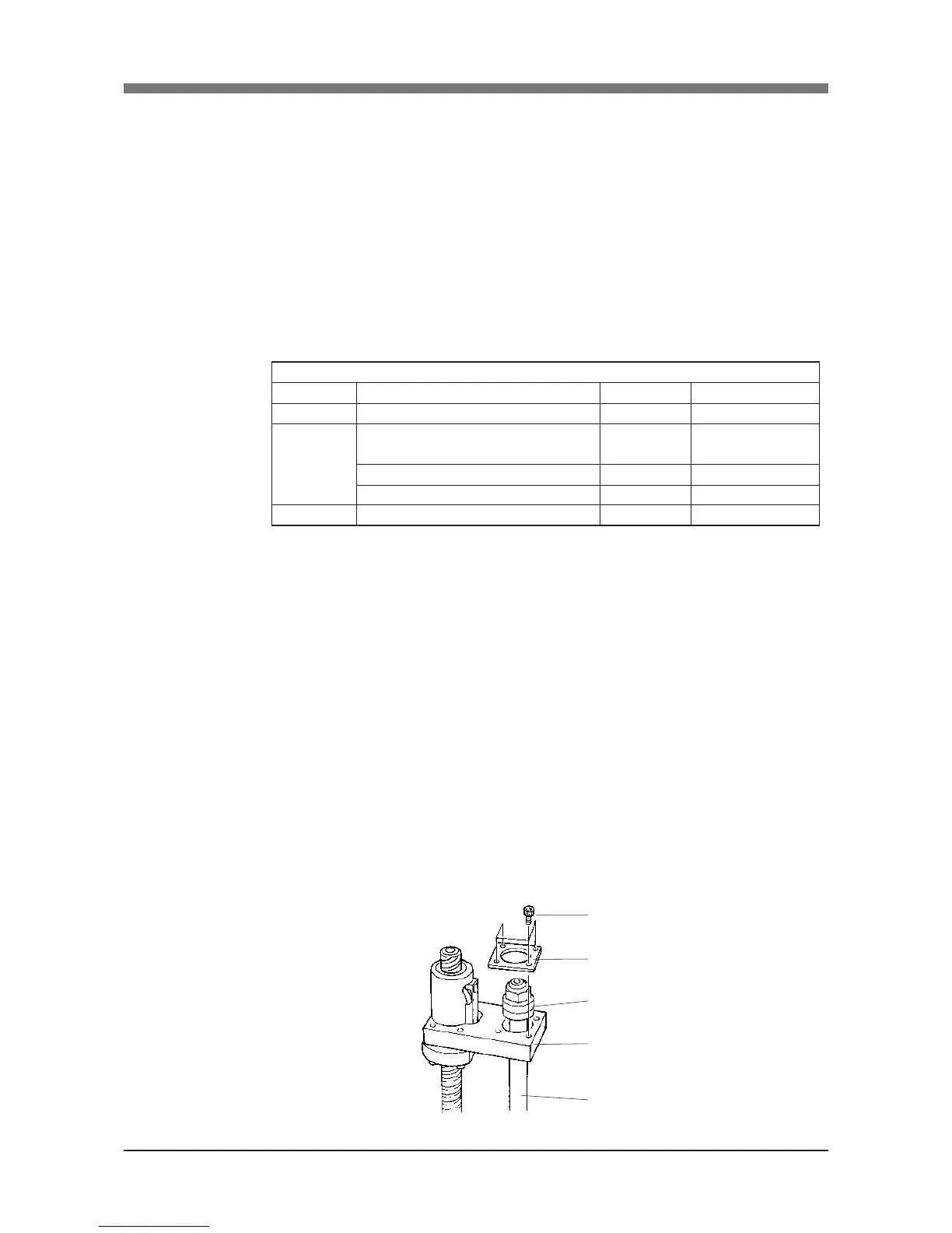
6) Remove the bolts (M4×8L, 4 pieces) securing the bearing to the upper end
of the spline and remove the spline mount plate, spline and bearing from
the holder. (See Fig. 5-11.)
 Loading...


