3-55
CHAPTER 3 Installation
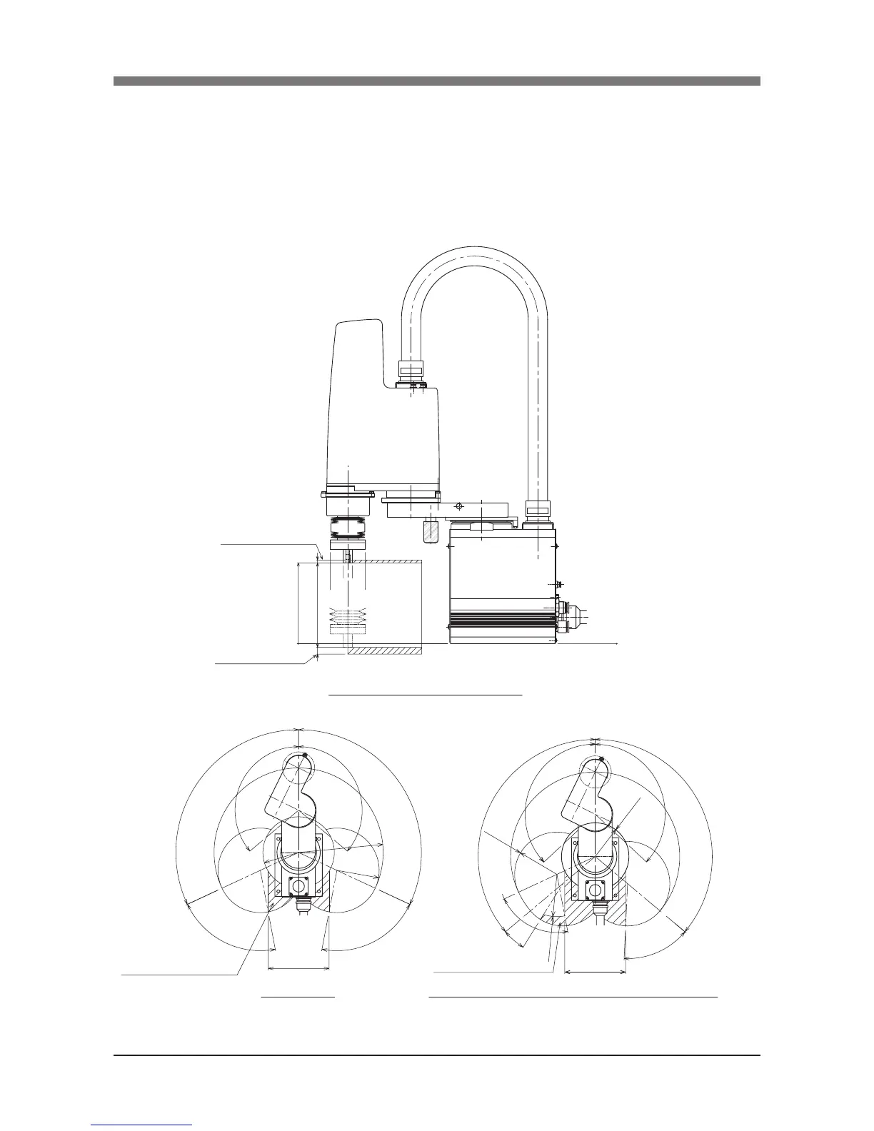
8 Working Envelope and Mechanical Stopper
Positions for Maximum Working Envelope
Working envelope of each robot and mechanical stopper positions for the maxi-
mum working envelope are shown in Fig. 3-69 to Fig. 3-76.
5
150
0
12
144.5±2
0
115°
130°
R106
76°
180
76°
R125
130°
R250
115°
130°
133°
R125
76°
18°
R125
180
53°
R100
133°
130°
Working envelope
Manipulator interference area
X and Y-axis mechanical stopper positions (maximum working envelope)
R6YXCH250 (Z-axis mechanical stopper position)
Z-axis upper end
mechanical stopper position
Z-axis lower end
mechanical stopper position
Manipulator interference area
Fig.3-69 R6YXCH250

 Loading...


