5-24
CHAPTER 5 Periodic Inspection
12) Remove the retaining ring for the wave generator and pull out the wave
generator from the bottom of the Y-axis arm. (See Fig. 5-16.)
13) Apply harmonic grease to the new wave generator. See Fig. 5-16 for
applying grease properly.
14) Fit a new O-ring into the O-ring groove on the wave generator. (See Fig. 5-16.)
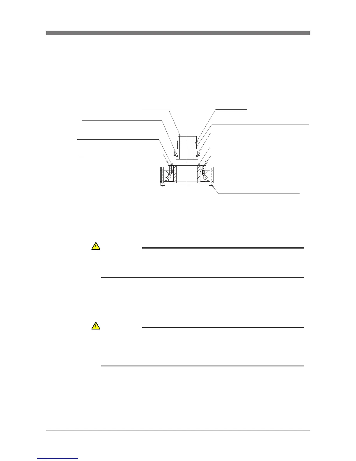
Apply grease to sufficiently fill in the ball space.
Apply grease to the thickness equal to the ball diameter.
Apply grease to entire oldham coupling.
Never remove these temporarily tightened bolts.
The axis will otherwise deviate from center.
Fit O-ring (supplied) into this groove
Harmonic drive will be damaged if O-ring is
caught out of groove.
O-ring : KN5-M181G-000
Remove the temporarily tightened bolts when assembling
Keep the
circular spline
from coming off when assembling
Wave generator
Retaining ring groove
Fit a new O-ring into the O-ring groove on the wave generator.
O-ring : KN3-M181H-000
Circular spline
Fig. 5-16
15) Insert the new wave generator into the Y-axis arm from the bottom, and
secure it with the retaining ring. The chamfered side of the retaining ring
should face downwards.
16) Apply harmonic grease to the circular spline.
See Fig. 5-16 for applying grease properly.
17) Remove the four bolts temporarily tightened to the new harmonic drive.
CAUTION
DO NOT ALLOW THE O-RING TO GET CAUGHT OUT OF THE GROOVE
DURING REASSEMBLY. A TROUBLE WILL OCCUR IF THE ROBOT IS
OPERATED WITH THE O-RING LEFT CAUGHT OUT OF THE GROOVE.
CAUTION
REMOVE ONLY THE FOUR BOLTS SHOWN IN FIG. 5-16 AT THIS POINT.
NEVER REMOVE THE BOLTS ON THE OPPOSITE SIDE. IF THEY ARE
REMOVED, THE HARMONIC DRIVE AXIS MAY DEVIATE FROM THE
CENTER CAUSING A TROUBLE.

 Loading...


