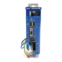
1.5 Part Names and Functions
15
1.5 Part Names and Functions
MECHATROLINK-II Communications Settings
The SW1 and the SW2 switches set the MECHATROLINK-II communications settings. Settings that
have been changed are enabled when the power is turned OFF and then ON again.
COM
ALM
RDY
FIL
L1
PWR
L2
U
V
W
CNBCNA
CN2
CN1
CN6
A/B
4
3
2
1
0
F
E
D
C
B
A
9
8
7
6
5
Power supply indicator (PWR)
Input voltage
Model
Ground terminal
Connector for MECHATROLINK-II
communications (CN6)
Refer to 3.4.6 Wiring the MECHATROLINK-
II Communication Connectors (CN6A and
CN6B).
Encoder connector (CN2)
Refer to 3.4.4 Wiring the Encoder Connec-
tor (CN2).
Connector for servomotor main circuit
cable (CNB)
Refer to 3.4.3 Wiring Connector for the Ser-
vomotor Main Circuit Cable (CNB).
Connector for power supply/
regenerative unit (CNA)
Refer to 3.4.2 Wiring Connector for the
Power Supply/Regenerative Unit
(CNA).
I/O signal connector (CN1)
Refer to 3.4 Main Circuit Wiring.
Rotary switch for reference filter
setting(FIL)
Refer to 6.1 Filter Setting.
Servo status indicator (RDY)
Alarm indicator (ALM)
Refer to 8 Troubleshooting.
Indicator for MECHATROLINK-II
communications status (COM)
Refer to 3.8.5 MECHATROLINK-II
Communications Status Indicator COM LED
and 8 Troubleshooting.
Connector for personal
computer (CN9)
Rotary switch for MECHATROLINK-II
station address setting (SW1)
Refer to 3.8 Setting for
MECHATROLINK-II Communications.
DIP switch for MECHATROLINK-II
communications setting (SW2)
Refer to 3.8 Setting MECHATROLINK-II
Communications.
TOEP_C710806_03A_1_0.book Seite 15 Montag, 2. Juli 2007 3:55 15

 Loading...