No.19S185-01
23/68
STC-MBE132POE / STC-MCE132POE
Product Specifications and User’s Guide
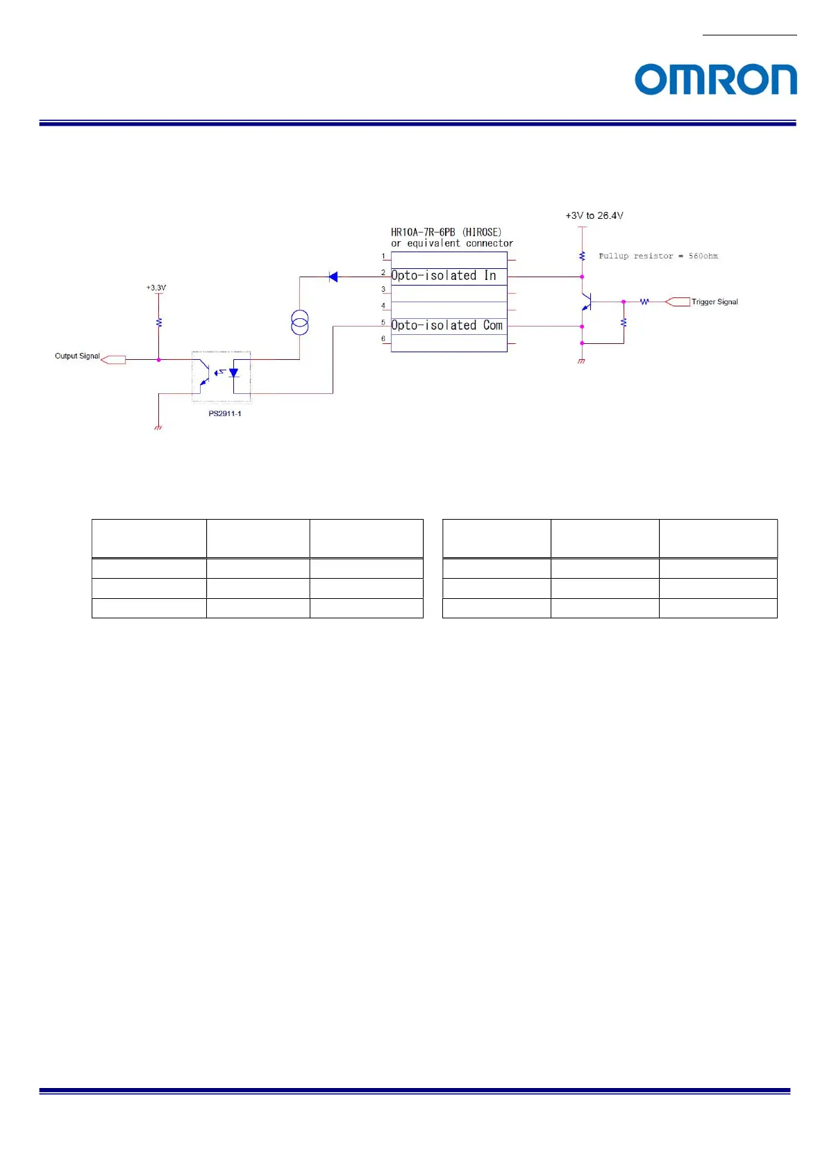
6.2.6.3 Measured External Trigger Signal Delay through Opt-Isolated Port (Line 0)
Measurement circuit
Positive polarity trigger signal
Negative polarity trigger signal
Pull-up voltage
Tdelay
Minimum active
pulse duration
Pull-up voltage
Tdelay
Minimum active
pulse duration
+3.3 V 8.2 μseconds
6 μseconds
+3.3 V 47 μseconds 6 μseconds
+12 V 4.6 μseconds
3 μseconds
+12 V 53.2 μseconds
3 μseconds
+24 V 4.4 μseconds
2 μseconds
+24 V 53.2 μseconds
2 μseconds
Note. Please use this measured delay as reference. The delay time may fluctuate depending on photo coupler
variation, pull-up voltage and pull-up resister.

 Loading...


