"
Main Circuit Terminals
Input Terminals (Top Section)
Terminal
symbol
Name and description
L1
N/L2
L3
Power input terminals
Three-phase, 200 to 230 VAC, 50/60 Hz input terminals. If a
3G3EV-AB
R is to be used in single-phase input mode, single-phase
200 to 240 VAC power with a frequency of 50/60 Hz must be input between
terminals R and S.
B1
B2
Braking resistor connection terminals (see note)
Terminals for connecting an optional braking resistor
Note
Before shipping, a resin plate is attached to each braking resistor connection ter-
minal to prevent incorrect wiring.
When connecting a braking resistor, always remove the resin plates with a pair of
long-nose pliers.
Output Terminals (Bottom Section)
Terminal
symbol
Name and description
U
V
W
Motor output terminals
Three-phase power output terminals for operating the motor. (Never connect
an AC power supply to these terminals.)
Ground terminal
Always use a ground terminal with a ground resistance of 100 Ω or less.
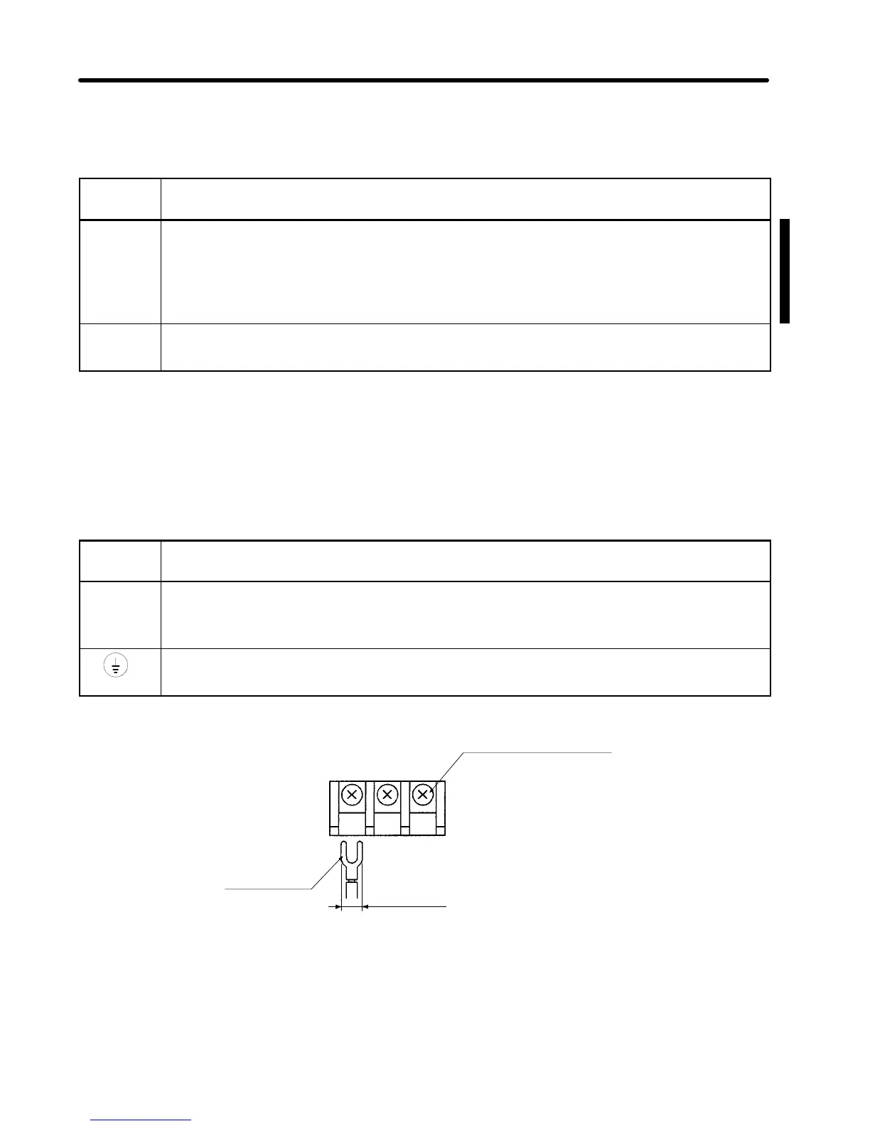
6.2 mm max.
Terminal block screw
(M3.5)
Crimp
terminal
Chapter 3