)
If the cable is long and may cause voltage drops, increase the wire size according to the
cable length.
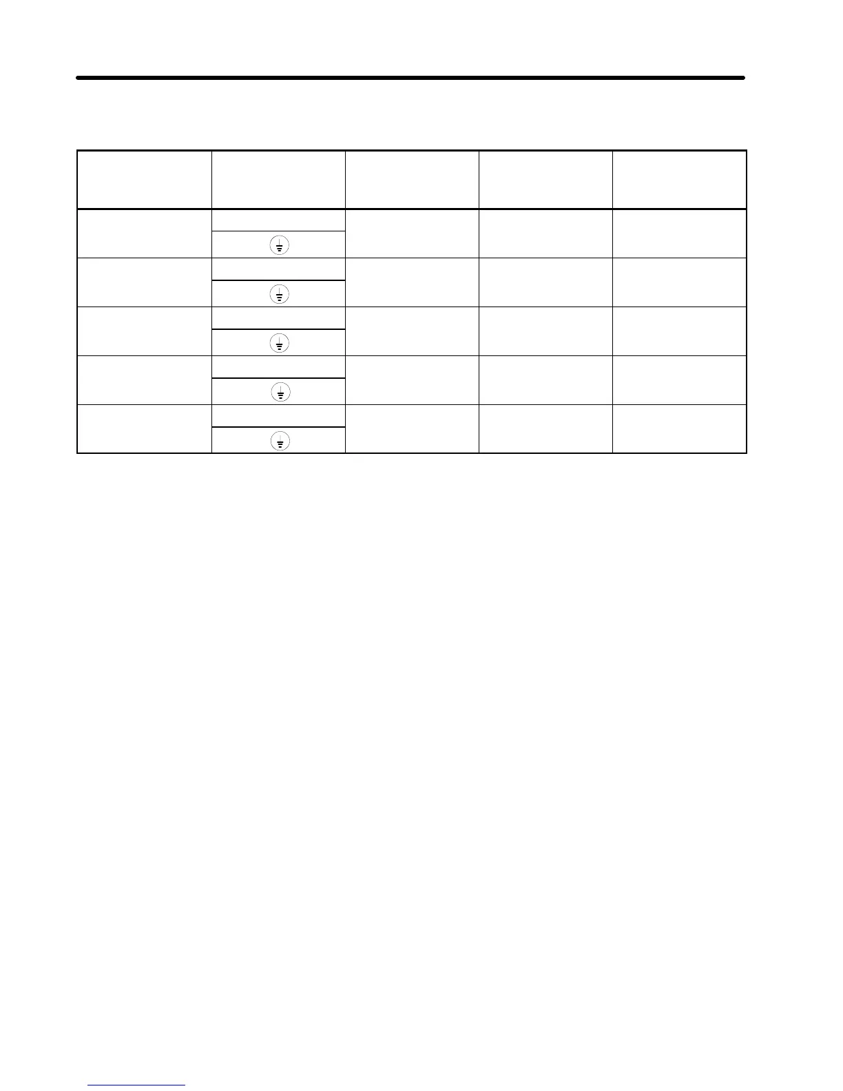
Model Terminal
symbol
Terminal screw Wire size
(mm
2
)
Molded-case
circuit breaker
capacity (A)
3G3EV-A2001R
RSTB1B2
M3.5 0.75 to 2 5
3G3EV-AB001R
UVW
3G3EV-A2002R
RSTB1B2
M3.5 0.75 to 2 5
3G3EV-AB002R
UVW
3G3EV-A2004R
RSTB1B2
M3.5 0.75 to 2 5
3G3EV-AB004R
UVW
3G3EV-A2007R
RSTB1B2
M3.5 0.75 to 2 10
3G3EV-AB007R
UVW
3G3EV-A2015R
RSTB1B2
M3.5 0.75 to 2 10
UVW
Determining the Wire Size
Determine the wire size for the main circuit so that line voltage drop is within 2% of the
rated voltage.
Line voltage drop V
D
is calculated as follows:
V
D
(V) = 3 x wire resistance (Ω/km) x wire length (m) x amperage (A) x 10
--3
Wiring on the Input Side of Main Circuit
Installing a Molded-case Circuit Breaker
Always connect the power input terminals (R, S, and T) and power supply via a molded-
case circuit breaker.
Installing a Ground Fault Interrupter
If a ground fault interrupter is to be connected to the wire on the primary side (R, S, and
T) of the main circuit, use either of the following interrupters to prevent malfunctions:
•Ground fault interrupter with a sensitivity amperage of 200 mA or more and with an
operating time of 0.1 second or more
•Ground fault interrupter with high-frequency countermeasures (for Inverter)
Chapter 3