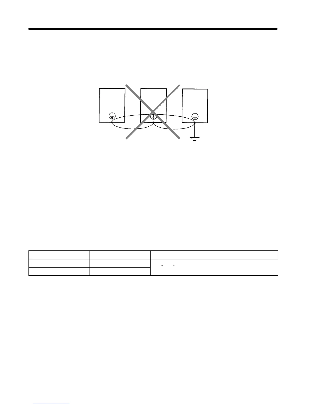
Note Minimize the total length (5 m or less) between the ground electrode and the
ground terminal, and also use a thick wire (1.25 m
2
or more). Leakage current
flows through the Inverter. Therefore, if the distance between the ground elec-
trode and the ground terminal is too long, potential on the ground terminal of the
Inverter will become unstable.
3-2-3 Wiring Control Circuit Terminals
The control signal line must be 50 m or less and must be separated from
the power line.
Wiring Sequence Input/Output Terminals
Wire the multi-function input1 terminals (S1 and SC) and the multi-function output 1 ter-
minals (PA and PC) as described below.
WirestobeUsed
Wire type Wire size Wire to be used
Single wire 0.5to1.25mm
2
Polyethylene-shielded cable
Stranded wire 0.5to0.75mm
2
Wiring Method
•Wire each terminal as follows:
a) Loosen the terminal screw with a thin-slotted screwdriver.
b) Insert the wire from underneath the terminal block.
c) Tighten the terminal screw firmly.
Chapter 3