'
Control Circuit Terminals
Input Terminals
Terminal
symbol
Name and description Interface
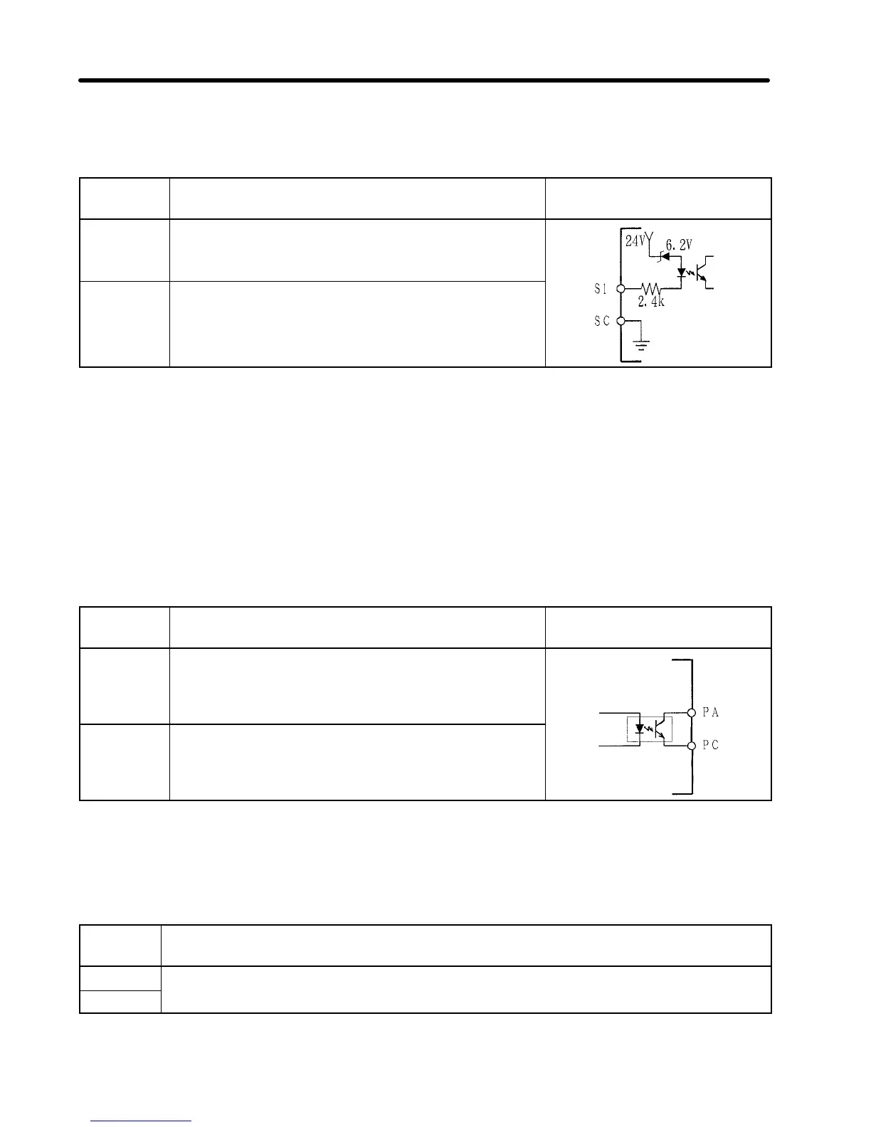
S1
Multi-function input (see notes 1 and 2)
SC
Multi-function input common
Input common for S1
24 VDC, 8mA
Note 1.
Constant no. 06 (n06) is used to set this function. This constant is factory-set to
“fault reset.”
Note 2.
Multi-function input 1 is allocated to both the control circuit terminal and input
channel. When either of them is turned on, multi-function input 1 becomes
valid. Therefore, if multi-function input 1 is to be used as “external fault (contact
b),” bit 4 of channel n +1 on the communication sidemust be set to 0. If this bit is
set to 1, an abnormal stop cannot be performed using external terminals.
Output Terminals
Terminal
symbol
Name and description Interface
PA
Multi-function output 1 (see note)
PB
Multi-function output common
Max. 48 VDC,
50 mA
Note
Constant no. 09 (n09) is used to set the function. This constant is factory-set to
“operation in progress.”
Transmission Terminals
Terminal
symbol
Name and description
+R
Data send-receive terminals
--R Terminals used to connect two-conductor cables for SYSMAC BUS.
Note
+R and +R, and --R and --R are internally shorted.
Chapter 3

 Loading...


