Note As the cable betweenthe Inverterandthe motor becomes longer, a high-frequen-
cy leakage current from the cable increases, causing the Inverter output current
to increase as well. This may also affect peripheral devices. To prevent this, ad-
just the carrier frequency according to the following standards:
Cable length of 50 meters or less: 10 kHz or less
Cable length of 50 to 100 meters: 5 kHz or less
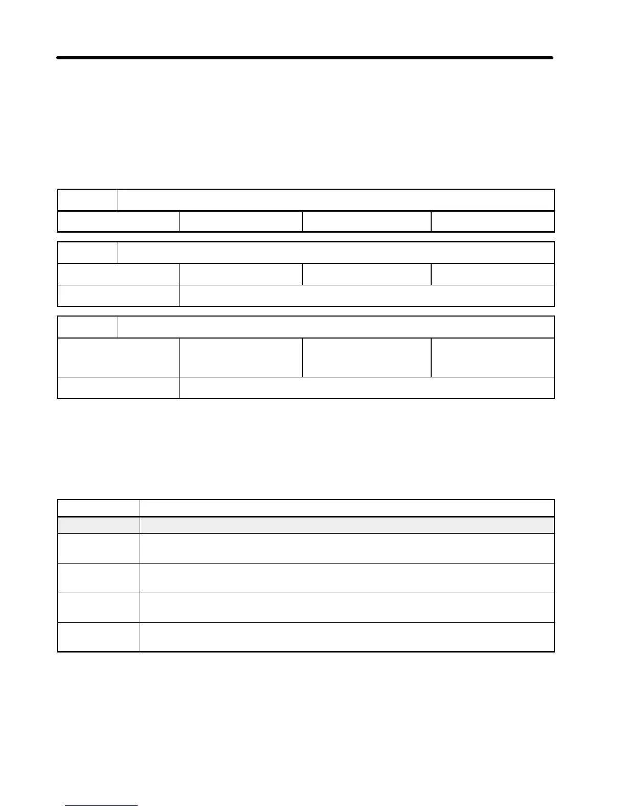
Over-torque Detection Function Selection
Setting range 0to4 Factory setting 0
Over-torque Detection Level
Setting range 30 to 200 (%) Factory setting 160 (%)
Unit of setting 1 (%)
Over-torque Detection Time
Setting range 0.1 to 10
(seconds)
Factory setting 0.1 (seconds)
Unit of setting 0.1 (seconds)
•When excessive load is applied to the equipment, the Inverter detects any increase in
output current and displays the fault according to the n09 and n10 settings (multi-func-
tion output selection).
•n50 is used to specify whether over-torque is to be monitored and specify the action to
be taken when over-torque is detected.
n50 setting Description
0 Inverter does not monitor over-torque.
1 Inverter monitors over-torque only when speed is matched. It continues
operation (issues warning) even after over-torque is detected.
2 Inverter monitors over-torque only when speed is matched. It discontinues
operation (through protection function) when over-torque is detected.
3 Inverter always monitors over-torque during operation. It continues
operation (issues warning) even after over-torque is detected.
4 Inverter always monitors over-torque during operation. It discontinues
operation (through protection function) when over-torque is detected.
•n51 is used to set the over-torque detection level. Specify this value in terms of the
percentage of the rated output current.
•n52 is used to set the over-torque detection time (in seconds).
Chapter 4
 Loading...


