9-3
Parame-
ter No.
Refer-
ence
page
Changes
during
opera-
tion
Default
setting
Unit
of set-
ting
Set-
ting
range
DescriptionName
n06 STOP/RESET
Key function
selection
Used to select the stop method in remote
mode with n02 for operation mode selec-
tion set to 1.
0: STOP/RESET Key of the Digital Opera-
tor enabled.
1: STOP/RESET Key of the Digital Opera-
tor disabled.
0, 1
1 0 No 5-7
n07 Frequency
selection in lo-
cal mode
Used to set the input method for the fre-
quency reference in local mode.
0: The FREQ adjuster of the Digital Opera-
tor enabled.
1: Key sequences on the Digital Operator
enabled.
0, 1
1 0 No 5-9
n08 Key sequential
frequency set-
ting
Used to enable the Enter Key for setting
the frequency reference with the Increment
and Decrement Keys.
0: The value is entered with the Enter Key
pressed.
1: The value is enabled when the value is
input.
0, 1
1 0 No 5-14
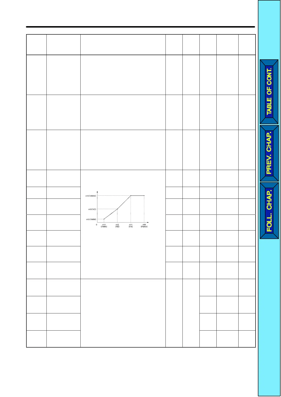
n09 Maximum fre-
quency (FMAX)
Used to set the V/f pattern as the basic
characteristic of the Inverter with output
voltage per frequency set.
50.0 to
400
0.1 Hz
(see
note)
60.0 No 5-4
n10 Maximum volt-
age (VMAX)
Output
voltage
1 to
255
1 V 200 No 5-4
n11 Maximum volt-
age frequency
(FA)
0.2 to
400
0.1 Hz
(see
note)
60.0 No 5-4
n12
Middle output
frequency (FB)
Frequency
(Hz)
0.1 to
399
0.1 Hz
(see
note)
1.5 No 5-4
n13
Middle output
frequency volt-
age (VC)
Note Set the parameters so that the fol-
lowing condition will be satisfied.
n14
x n12 < n1
1
x
n09
1 to
255
1 V 12 No 5-4
n14
Minimum output
frequency
(FMIN)
Note The
value set in n15 will
be ignored if
arameters n14 and n12 are the
0.1 to
10.0
0.1 Hz 1.5 No 5-4
n15
Minimum output
frequency volt-
age (VMIN)
same in value.
1 to 50
1 V 12.0 No 5-4
n16 Acceleration
time 1
Acceleration time: The time required to go
from 0% to 100% of the maximum fre-
quency.
0.0 to
999
0.1 s
10.0 Yes 5-15
n17 Deceleration
time 1
Deceleration time: The time required to go
from 100% to 0% of the maximum frequen-
cy.
Note The actual acceleration or decel-
10.0 Yes 5-15
n18 Acceleration
time 2
Note The actual acceleration or decel-
eration time is obtained from the
following formula.
Acceleration/Deceleration time =
10.0 Yes 5-15
n19 Deceleration
time 2
Acceleration/Deceleration
=
(Acceleration/Deceleration time
set value) × (Frequency reference
value)
÷ (Max. frequency)
10.0 Yes 5-15
List of Parameters Chapter
9
 Loading...


