2-12
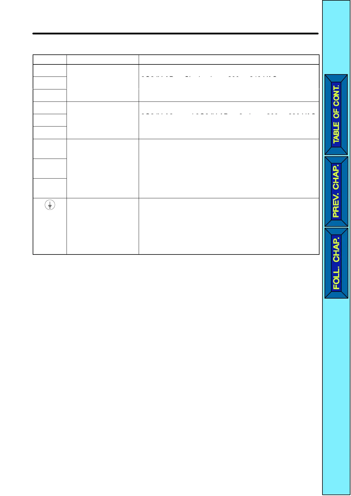
H Main Circuit Terminals
Symbol Name Description
R/L1
Power supply input
3G3JV-A2j: 3-phase 200 to 230 VAC
3G3JV ABj Si l h 200 t 240 VAC
S/L2
term
na
s
3G3JV-ABj: Single-phase 200 to 240 VAC
Note Connect single phase input to terminals R/L1
T/L3
Note Connect single-phase input to terminals R/L1
and S/L2.
U/T1
Motor output
3-phase power supply output for driving motors.
3G3JV A2j d 3G3JV ABj 3 h 200 t 230 VAC
V/T2
term
na
s
3G3JV-A2j and 3G3JV-ABj: 3-phase 200 to 230 VAC
Note The maximum output voltage corresponds to the
W/T3
Note The maximum output voltage corresponds to the
power supply input voltage of the Inverter.
+1
Connection terminals
+1 and +2:
Connect the DC reactor for suppressing harmonics to
terminals +1 and +2.
Wh d i i h I i h DC i h DC
+2
DC reactor
connection terminals
–
When driving the Inverter with DC power, input the DC
power to terminals +1 and –.
(Terminal +1 is a positive terminal )
–
+
an
–:
DC power supply
input terminals
erm
na
+
s a pos
ve
erm
na
.
Ground terminal Be sure to ground the terminal under the following
conditions.
3G3JV-A2j: Ground at a resistance of 100 Ω or less.
3G3JV-ABj: Ground at a resistance of 100 Ω or less.
Note Be sure to connect the ground terminal directly
to the motor frame ground.
Design Chapter
2
 Loading...


