2-13
H Control Circuit Terminals
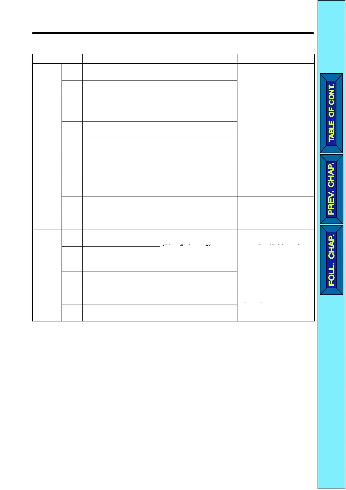
Symbol Name Function Signal level
Input
S1 Forward/Stop Forward at ON. Stops
at OFF.
Photocoupler
8 mA at 24 VDC
S2 Multi-function input 1
(S2)
Set by parameter n36
(Reverse/Stop)
S3 Multi-function input 2
(S3)
Set by parameter n37
(External fault: Normal-
ly open)
S4 Multi-function input 3
(S4)
Set by parameter n38
(Fault reset)
S5 Multi-function input 4
(S5)
Set by parameter n39
(Multi-step reference 1)
SC Sequence input com-
mon
Common for S1
through S5
FS Frequency reference
power supply
DC power supply for
frequency reference
use
20 mA at 12 VDC
FR Frequency reference
input
Input terminal for fre-
quency reference use
0 to 10 VDC (20 kΩ)
FC Frequency reference
common
Common for frequency
reference use
Output
MA Multi-function contact
output (Normally open)
Set by parameter n40
(during running)
Relay output
1 A max. at 30 VDC
MB Multi-function contact
output (Normally
closed)
1 A max. at 250 VAC
MC Multi-function contact
output common
Common for MA and
MB use
AM Analog monitor output Set by parameter n44
(Output frequency)
2 mA max. at 0 to
10 VDC
AC Analog monitor output
common
Common for AM use
Note Functions in parentheses are default settings.
Design Chapter
2
 Loading...


