EasyManuals Logo

Omron SYSDRIVE 3G3JV Series User Manual

Omron SYSDRIVE 3G3JV Series
166 pages
To Next Page IconTo Next Page
To Previous Page IconTo Previous Page
Page #22 background imageLoading...
Page #22 background image
2-14
H Selecting Input Method
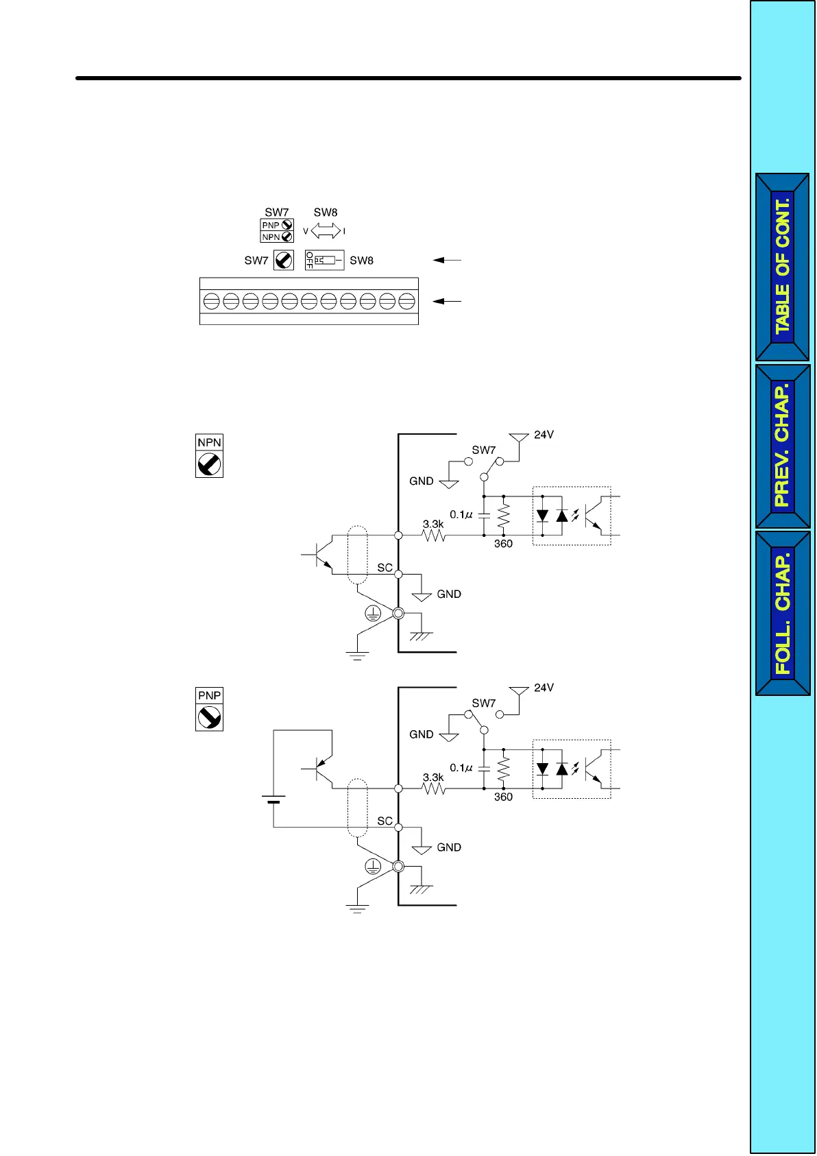
Switches
SW7 and SW8, both of which are located above the control circuit terminals,
are used for input method selection.
Remove the front cover and optional cover to use these switches.
Selector
Control circuit
terminal block
D Selecting Sequence Input Method
By using SW7, NPN or PNP input can be selected as shown below.
24 VDC
S1 to 5
S1 to 5
Design Chapter
2

Table of Contents

Questions and Answers:

Question and Answer IconNeed help?

Do you have a question about the Omron SYSDRIVE 3G3JV Series and is the answer not in the manual?

Omron SYSDRIVE 3G3JV Series Specifications

General IconGeneral
ModelSYSDRIVE 3G3JV Series
CategoryInverter
Output Frequency Range0.1 to 400Hz
Frequency Range50/60Hz
Control MethodPWM Control
Overload Capacity150% for 1 minute
Protection FeaturesOvercurrent, Overvoltage, Undervoltage, Overheat
Cooling MethodFan Cooling
Ambient Temperature-10 to 50°C
Operating Temperature-10 to 50°C
Storage Temperature-20°C to +65°C
Humidity90% RH or less (non-condensing)
Altitude1000m or less
Vibration5.9 m/s² or less
Braking UnitBuilt-in
CommunicationRS-485
Voltage Class200V class, 400V class
Input Voltage3-phase 200 to 240V AC, 3-phase 380 to 480V AC

Related product manuals