2-31
H Wiring Frequency Reference Input Terminals
Wire
the frequency reference input terminals FR and FC as described below for execut
-
ing
frequency references with
the D/A Unit for digital-to-analog data conversion or ex
-
ternal power supply.
D Wires Used
Use
shielded, twisted-pair wires for wiring in order to prevent the Inverter from malfunc
-
tioning due to noise.
Wire type Wire size Wire to be used
Single wire 0.5 to 1.25 mm
2
Polyethylene-shielded cable
Stranded wire 0.5 to 0.75 mm
2
o yet y e e s e ded cab e
for measurement use
D Solderless Terminals for Frequency Reference Input Terminals
The use of solderless terminals for the frequency reference input terminals is recom-
mended because solderless terminals are easy to connect securely.
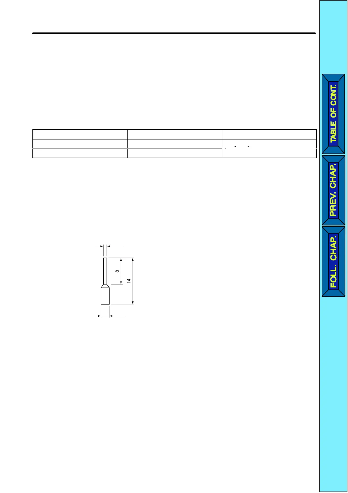
Note Make
sure
that the wire size is 0.5 mm
2
when using the following solderless termi
-
nal.
1.0 dia.
2.6 dia. (Size: mm)
Model: Phoenix Contact’s A1 0.5-8 WH
D Wiring Method
•The
wiring method of the frequency reference input terminals is the
same as that of the
control circuit terminals.
•Always
separate the control signal line from the main
circuit cables and other power
cables.
•Connect
the shield to the ground terminal of the
Inverter
. Do not connect the shield to
the load.
•Cover
the shield with tape so that the shield will
not come into contact with other signal
wires or machines.
Design Chapter
2
 Loading...


