2-33
D Wiring the Power Supply
Make sure that the Inverter and Noise Filter are grounded together.
•Always
connect the power input terminals (R/L1, S/L2, and T/L3) and power supply via
a dedicated Noise Filter.
•Reduce the length of the ground wire as much as possible.
•Locate
the Noise Filter as close as possible to the Inverter
. Make sure that the cable
length between the Noise Filter and the Inverter does not exceed 40 cm.
•The following Noise Filters are available (all footprint type).
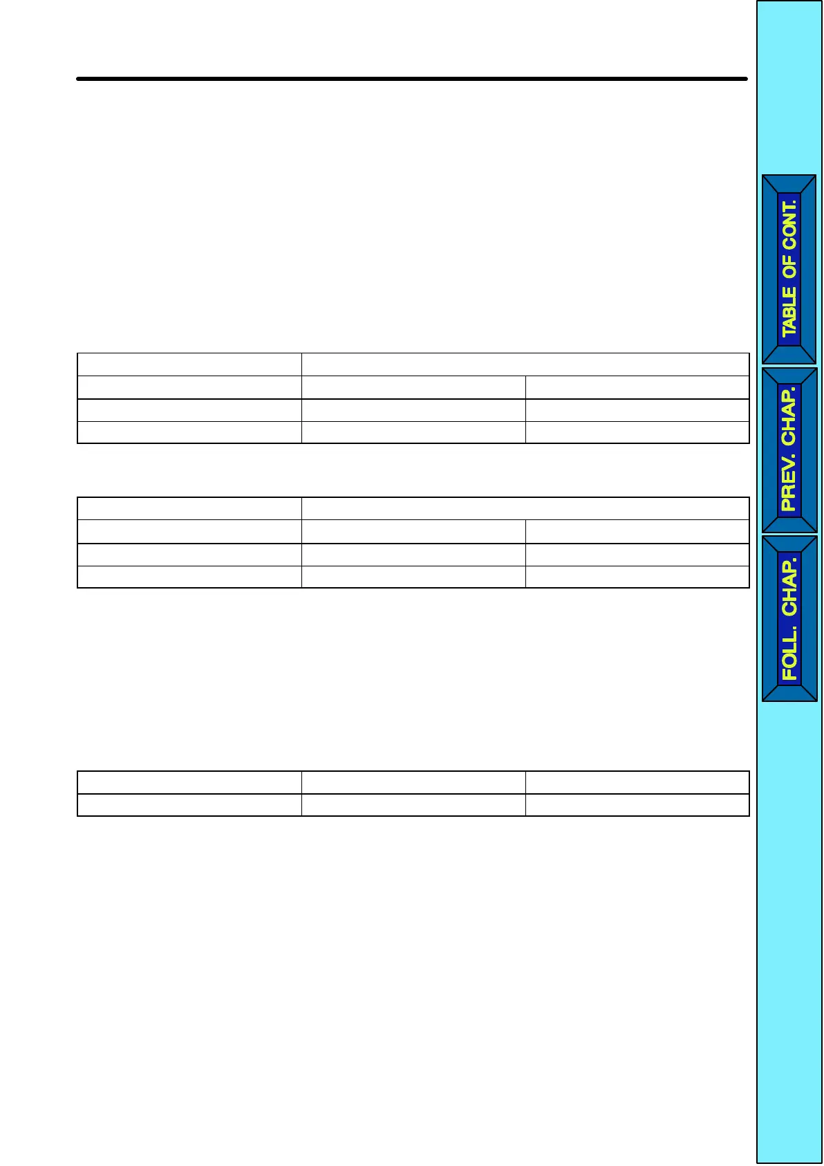
3-phase 200-VAC Noise Filter
Inverter 3-phase 200-VAC Noise Filter
Model 3G3JV- Model 3G3JV- Rated current (A)
A2001/A2002/A2004/A2007 PFI2010-E 10
A2015/A2022 PFI2020-E 20
Single-phase 200-VAC Noise Filter
Inverter Single-phase 200-V Noise Filter
Model 3G3JV- Model 3G3JV- Rated current (A)
AB001/AB002/AB004 PFI1010-E 10
AB007/AB015 PFI1020-E 20
D Connecting a Motor to the Inverter
•When
connecting a motor to the Inverter
, be sure to use a cable with a braided shield.
•Reduce
the length of
the cable as short as possible and ground the shield on the Invert
-
er
side as well as the motor side. Make sure that the cable length between the Inverter
and the motor does not exceed 20 cm.
Furthermore, connect a clamp core (Clamp Fil
-
ter) close to the output terminals of the Inverter.
Product Model Manufacturer
Clamp Filter 2CAT3035-1330 TDK
D Wiring a Control Cable
•Be sure to connect a cable with a braided shield to the control circuit terminals.
•Ground the shield on the Inverter side only.
Design Chapter
2
 Loading...


