1-5
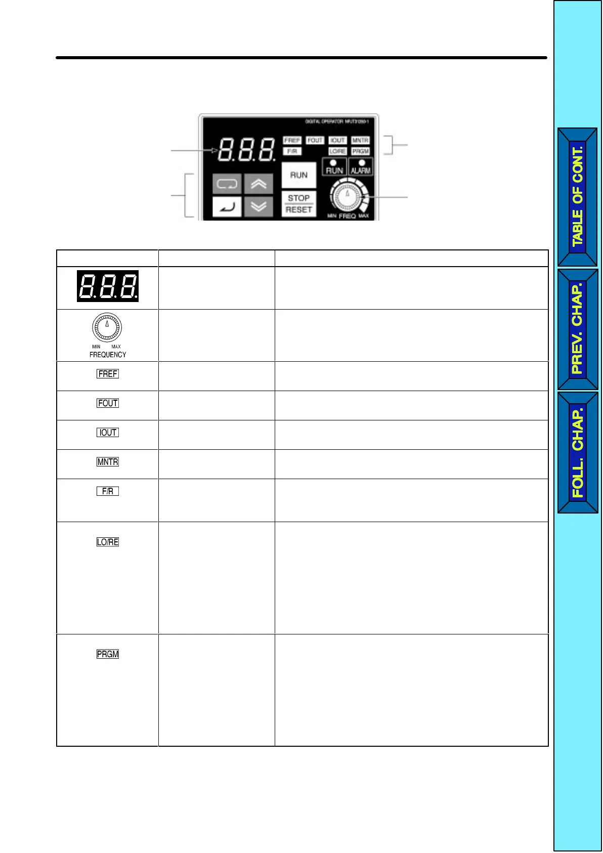
H Digital Operator
Data display
Keys
Indicators
(Setting/Monitor
item indicators)
FREQ adjuster
Appearance Name Function
Data display Displays relevant data items, such as frequency
reference, output frequency, and parameter set
values.
FREQ adjuster Sets the frequency reference within a range
between 0 Hz and the maximum frequency.
FREF indicator The frequency reference can be monitored or set
while this indicator is lit.
FOUT indicator The output frequency of the Inverter can be
monitored while this indicator is lit.
IOUT indicator The output current of the Inverter can be
monitored while this indicator is lit.
MNTR indicator The values set in U01 through U10 are
monitored while this indicator is lit.
F/R indicator The direction of rotation can be selected while
this indicator is lit when operating the Inverter
with the RUN Key.
LO/RE indicator The operation of the Inverter through the Digital
Operator or according to the set parameters is
selectable while this indicator is lit.
Note This status of this indicator can be only
monitored
while the Inverter
is in operation.
Any RUN command input is ignored while
this indicator is lit.
PRGM indicator The parameters in n01 through n79 can be set or
monitored while this indicator is lit.
Note While the Inverter is in operation, the pa-
rameters can be only monitored and only
some parameters can be changed. Any
RUN command input is ignored while this
indicator is lit.
Overview Chapter
1
 Loading...


