5-57
5
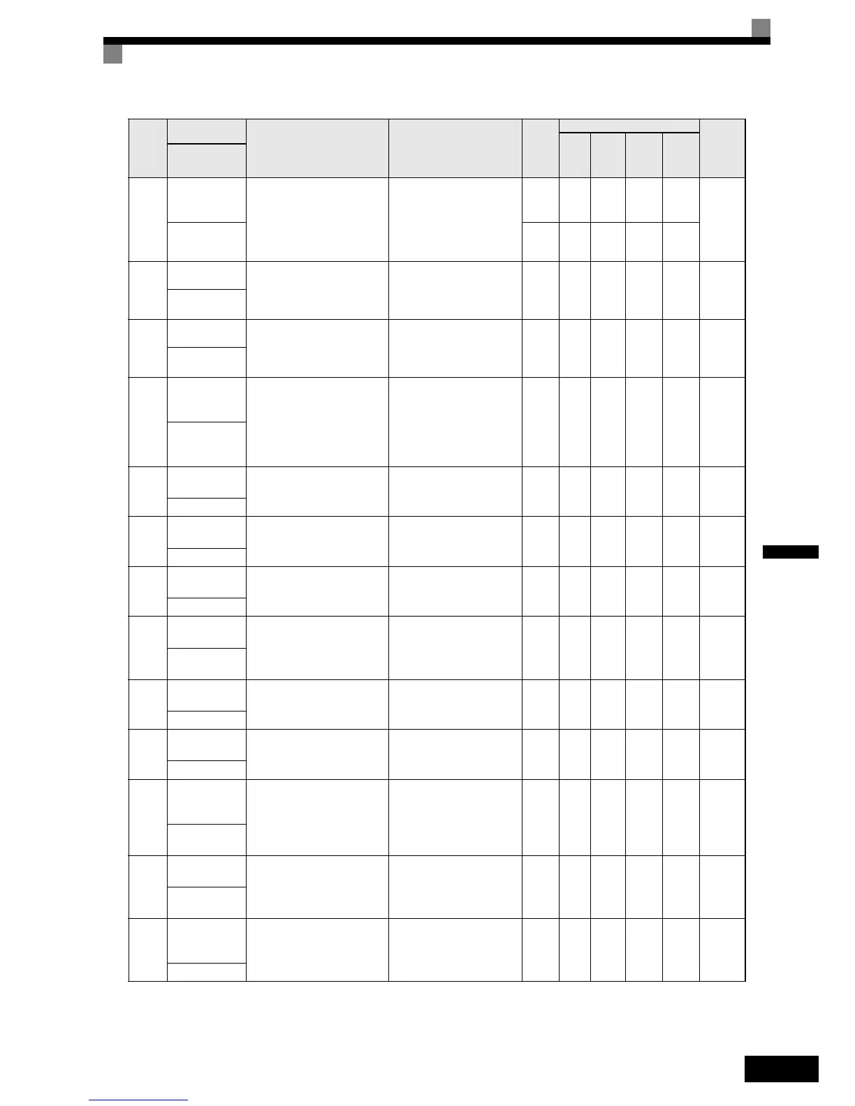
U1-20
Frequency refer-
ence after soft-
starter
Monitors the frequency refer-
ence after the soft starter.
This frequency value does not
include compensations, such as
slip compensation.
The unit is set in o1-03.
10 V: Max. frequency
(0 to ± 10 V possible)
0.01H
z
AA A -
53H
SFS Output 0.01% - - - A
U1-21
ASR input
Monitors the input to the speed
control loop.
The maximum frequency corre-
sponds to 100%.
10 V: Max. frequency
(0 to ± 10 V possible)
0.01% - - A A 54H
ASR Input
U1-22
ASR output
Monitors the output from the
speed control loop.
The maximum frequency corre-
sponds to 100%.
10 V:Max. frequency
(0 to ± 10 V possible) 0.01% - - A A 55H
ASR output
U1-25
DI-16H2 input
status
Monitors the reference value
from a DI-16H2 Digital Refer-
ence Card.
The value will be displayed in
binary or BCD depending on
user constant F3-01.
(Cannot be output.) - A A A A
58H
DI-16 Reference
U1-26
Output voltage
reference (Vq)
Monitors the Inverter internal
voltage reference for motor sec-
ondary current control.
10 V: 200 VAC (400 VAC)
(0 to ± 10 V possible)
0.1 V - A A A 59H
Voltage Ref(Vq)
U1-27
Output voltage
reference (Vd)
Monitors the Inverter internal
voltage reference for motor
excitation current control.
10 V: 200 VAC (400 VAC)
(0 to ± 10 V possible)
0.1 V - A A A 5AH
Voltage Ref(Vd)
U1-28
Software No.
(CPU)
(Manufacturer’s CPU software
No.)
(Cannot be output.) - A A A A 5BH
CPU ID
U1-32
ACR output of q
axis
Monitors the current control
output value for the motor sec-
ondary current.
10 V: 100%
(0 to ± 10 V possible)
0.1
%
-AA A5FH
ACR(q)
Output
U1-33
ACR output of d
axis
Monitors the current control
output value for the motor exci-
tation current.
10 V: 100%
(0 to ± 10 V possible)
0.1
%
-AA A 60H
ACR(d) axis
U1-34
OPE fault
parameter
Shows the first parameter num-
ber when an OPE fault is
detected.
(Cannot be output.) - A A A A 61H
OPE Detected
U1-35
Zero servo
movement
pulses
Shows the number of PG pulses
of the movement range when
zero servo was activated. The
shown value is the actual pulse
number times 4.
(Cannot be output.) - - - A A 62H
Zero Servo
Pulse
U1-40
Cooling fan
operating time
Monitors the total operating
time of the cooling fan. The
time can be set in
02-10.
(Cannot be output.)
1
hr.
AA A A 67H
FAN Elapsed
Time
U1-41
Inverter Heat-
sink Tempera-
ture
Shows the inverter heatsink
temperature measured by the
IGBT thermal protection sen-
sor.
(Cannot be output) °C A A A A 68H
Actual Fin Temp
Param-
eter
Num-
ber
Name
Description
Output Signal Level During
Multi-Function Analog Output
Min.
Unit
Control Methods
MEMO-
BUS
Register
V/f
Open
Loop
Vector
Closed
Loop
Vector
Closed
Loop
Vector
(PM)
Display