Installing and connecting the Crocus CNV Crocus CNV
14 User manual
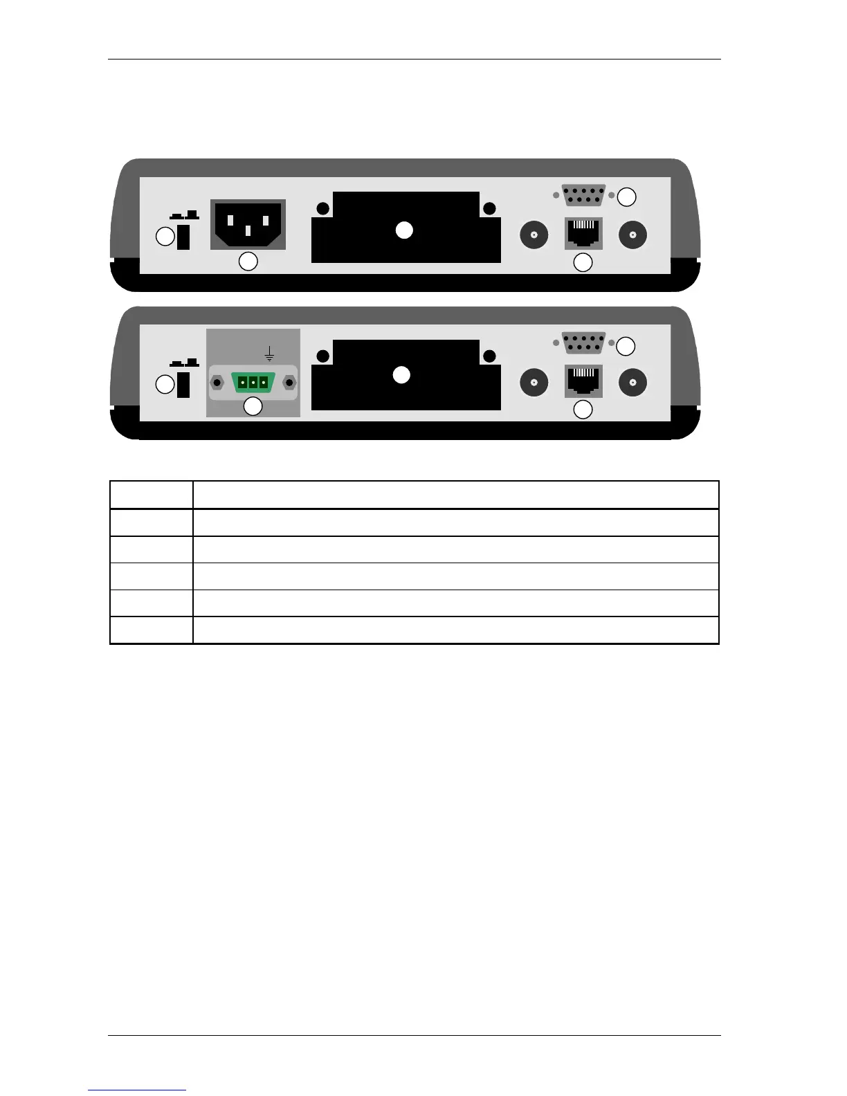
2.5.1 Table Top connections
All the connections have to be made at the back of the Crocus CNV Table Top. The following figure gives
a rear view of the Crocus CNV TT.
The following table labels the different parts located at the back of the Crocus CNV TT.
Number Part
1 power switch
2 power inlet
3 DTE interface slot
4 G703 onboard interface
5 auxiliary connector (also called control or NMS connector)
CTRL
OUT IN
WARNING! SEE BOTTOM
PWR
ON OFF
CTRL
OUT IN
WARNING! SEE BOTTOM
PWR
ON OFF
~ ~
- 48V +
1
1
2
3
4
5
2
3
4
5