Crocus CNV Step-by-step configuration
User manual 53
5.1 Reading the configuration settings
As this chapter explains the basic configuration of the Crocus CNV, it contains some DIP switch
configuration tables and a lot of TMA attribute strings. To enable you to read this information in a correct
manner, this section explains the structure of such tables and strings.
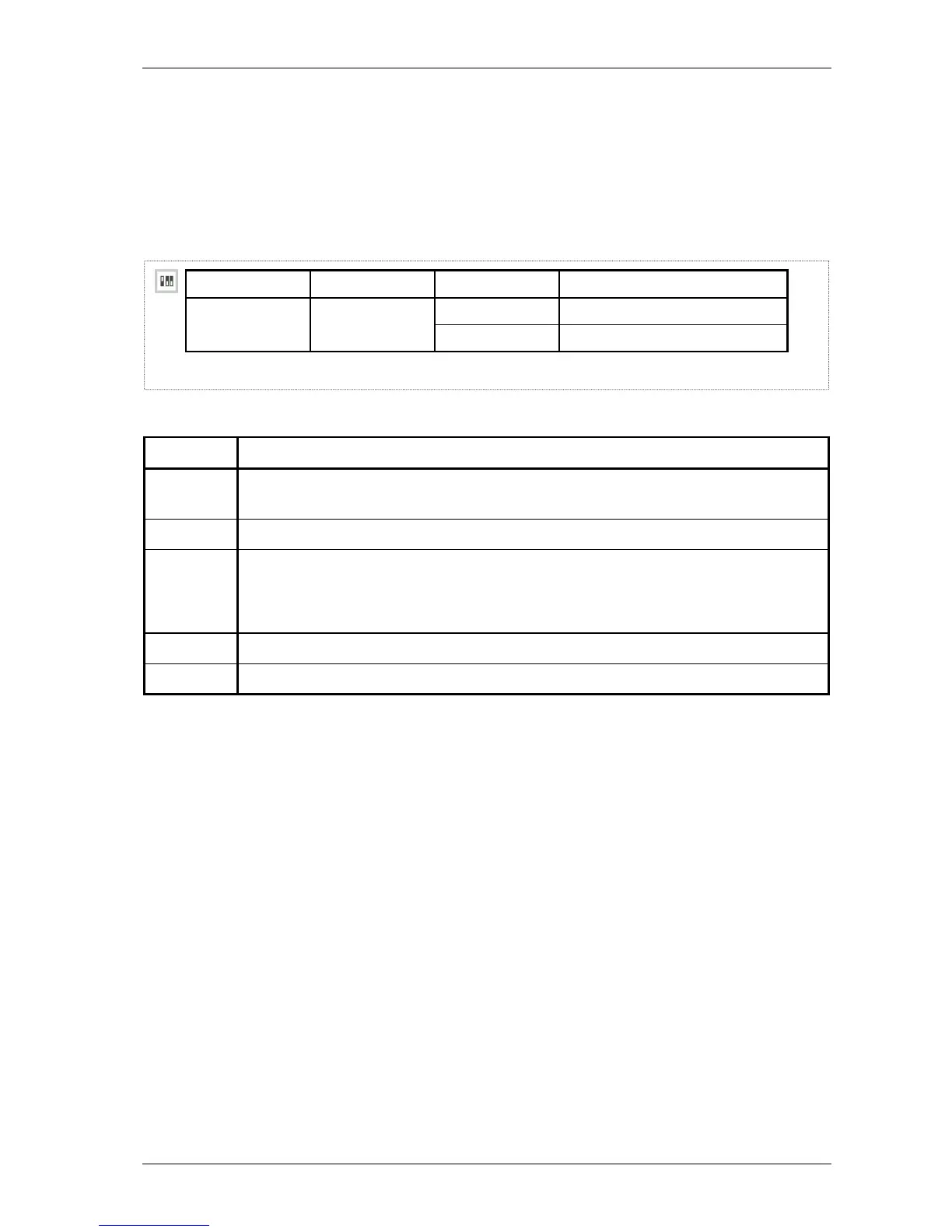
DIP switch configuration table
A DIP switch configuration table has the following layout:
DIP switch name DS2 no. Setting Function
1
on
Start up from flash memory. start-up mode
off Start up in boot mode.
1 2 3 4 5
The following table explains the DIP switch configuration table layout.
Number This position displays …
1 the DIP switch icon. It indicates that the table which follows is a DIP switch configuration
table.
2 the DIP switch name.
3 the DIP switch position on the DIP switch bank.
The abbreviations mean the following:
DS2 no. 2: DIP switch bank number 2, switch position number 2
4
the possible settings of the DIP switch: on and off. The default setting is printed in bold.
5 the function associated with the corresponding DIP switch setting.