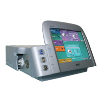
PULSAR
2
ESP
Installation and Operating Manual
OPTIKON 2000
Cod. 111007EN Rev.E
6-2
NOTE:
It is the responsibility of the user to clean and sterilize the handpieces, tips, I/A tubing and other
microsurgical reusable instruments.
4. Connect the "GAS FILTER" supplied with the unit (Fig.3, No.4) to the rear
panel.
5. Connect the tube supplied with the unit between "FILTER OUTLET" (Fig.3,
No.5) and "AIR INPUT" (Fig.3, No.10).
6. Check that the pressure level of the compressed air supply corresponds to
the value indicated on the rear panel (from 500 to 800 KPa –
72 to 116 PSI
).
7. Using the tube for compressed air supply (122001) connect the "GAS INLET"
(Fig.3, No.3) input of the gas filter to the compressed air supply line.
8. Connect the linear footswitch cable to the "FOOTSWITCH CONTROL" socket
(Fig.3, No.9). Turn the retaining ring clockwise to secure the plug.
9. If the cart with automatic I.V. POLE is available, connect it to the I.V. POLE
connector (Fig.3, No.12). The PULSAR
2
tests if the automatic I.V. pole is
present when the unit is switched on; therefore be sure that the pole is
connected and powered.
10. Check that the available A.C. supply voltage corresponds to the one selected
on the rear panel.
11. Connect the A.C. power cord to the A.C. power input (Fig.3, No.8) and then
plug it into the cart receptacle or into an earthed (grounded) electricity
wall outlet. Turn power on.
12. If the 181004/181001 cart is used, leave the PULSAR
2
mains switch into the
on position and utilise the cart mains switch to power on/off the system.