PULSAR
2
ESP
Installation and Operating Manual
OPTIKON 2000
Cod. 111007EN Rev.E
7-5
7.2 EQUIPMENT LAYOUT
This section contains information on the equipment layout. All operating controls
and adjustments are identified and described further on. Sockets and other
elements on the front panel are described in Fig. 1 Left side (pump side) of the
equipment is described in Figure 2. Rear panel connectors are identified in Fig. 3.
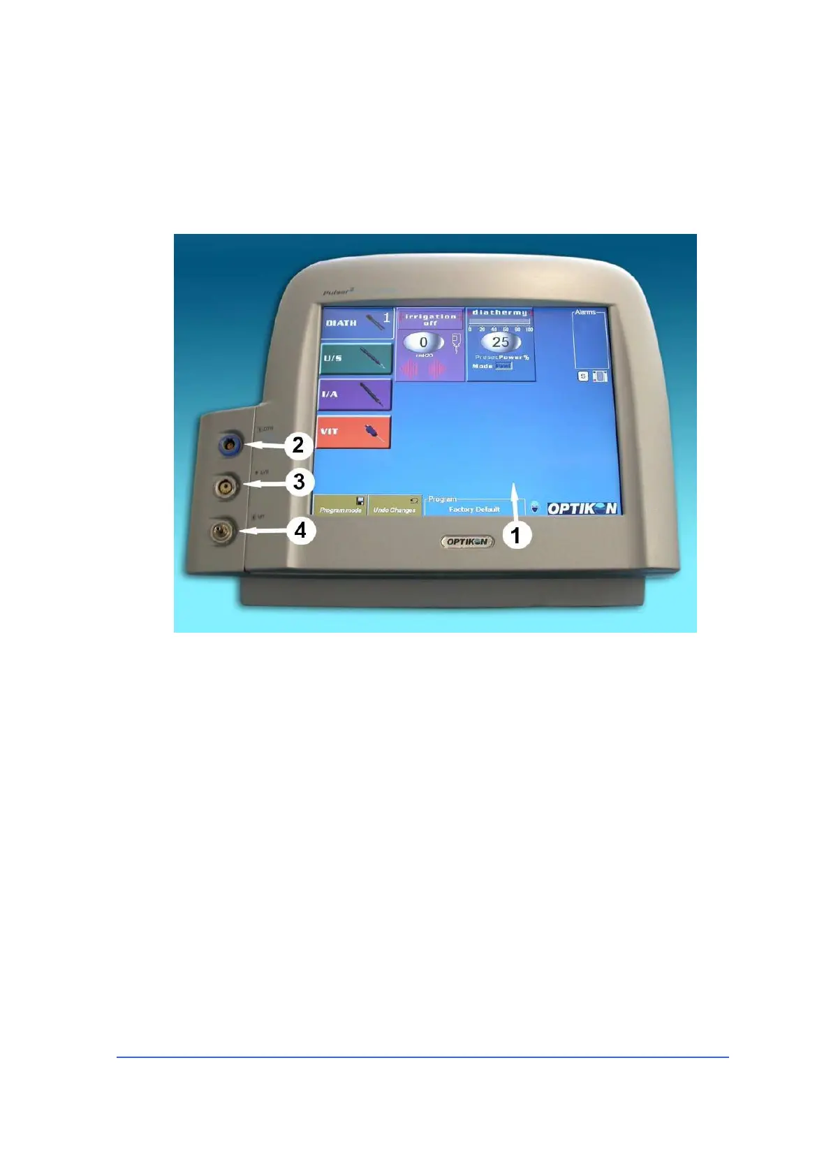
Front view (Fig. 1)
1) LCD TOUCH-SCREEN DISPLAY
By means of this LCD touch-screen the user can
- activate the proper functions
- setup all parameters
- read all actual and preset values
- read warnings and error messages
- program the equipment and footswitch
2) DIATHERMY SOCKET
Bipolar diathermy handpiece cable fits into this socket.
3) U/S (Phaco) SOCKET
Phaco handpiece connector plugs into this socket.
4)
VIT SOCKET
The activation line of the disposable vitrectomy handpiece plugs into this socket