10
Connection
6 Connection
This chapter explains how to connect the driver with the motor, power supply cable, and I/O signals.
6.1 Connecting the motor and driver (CN3)
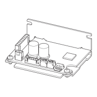
Insert the motor cable connector into the motor connector (CN3) on the driver.
When extending the motor cable, use a connection cable (sold separately).
The maximum extension distance including the cable length of the motor itself should be 2 m (6.6 ft.).
Note
•
Firmly insert the connector in position. Insecure connector connection may cause malfunction or damage to the
motor or driver.
•
Be sure to insert and pull out the connector while holding the connectors part. Do not apply any force in a direction
other than the direction of inserting and pulling out the connector. Applying improper force may cause damage to
the connector and driver.
CN3 pin assignment
Viewed from the direction of an arrow
in the right gure
1
2
3
4
5
6
7
8
•
Housing 43645-0800 (molex)
•
Terminal AWG22, 24: 43030-0001 (molex)
AWG26: 43030-0004 (molex)
CN1
+
-
CN3
Pin No. Lead wire color
*
Lead wire size
1 Gray (Black)
AWG222 Purple
3 Blue
4 Yellow
AWG26
5 Green
6 Orange
7 Red
8 Brown (White)
*
The color in parentheses ( ) indicates the 15 W type.
For lead wire type and connector type, all lead wire sizes are AWG22 (15W: AWG24).

 Loading...


