11
Connection
6.2 Connecting the power supply (CN1)
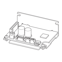
Insert the power supply cable connector into the power supply connector (CN1) on the driver.
Lead wire size: AWG22 (0.3 mm
2
)
Note
•
When connecting, pay attention to the polarity of the power supply. Connection with incorrect polarity may cause
damage to the driver.
•
Do not wire the power supply cable of the driver in the same cable duct with other power lines or motor cables.
•
When turning on the power again or inserting/pulling out the motor cable connector, turn o the power and wait
for at least 5 seconds before doing so.
CN1 pin assignment
Pin No. Lead wire color Lead wire size
Viewed from the direction of an
arrow in the right gure
1
2
Housing: 43645-0200 (molex)
Terminal: 43030-0001 (molex)
CN1
+
-
24 VDC±10%
+
−
1 Red
AWG22
2 Black
Note on power ON/OFF using a mechanical contact
•
When turning on or o the power supply using a mechanical
contact (breaker, electromagnetic switch, relay, etc.), do so only
the positive side (+) of the power supply using the mechanical
contact.
CN1
+
-
+
‑
DC power supply
Do not turn on or o the positive side (+) and the negative side (−) of the power supply simultaneously or
shut o only the negative side (−) of the power supply.
The main circuit and the control circuit in the driver are connected to the same ground. So the input current
of the main circuit ows round into the control circuit when the power supply is turned on or o, causing
damage to the control circuit or peripheral equipment.

 Loading...


