Connection
−39−
2 Installation and connection
2.6 Connecting the I/O signals
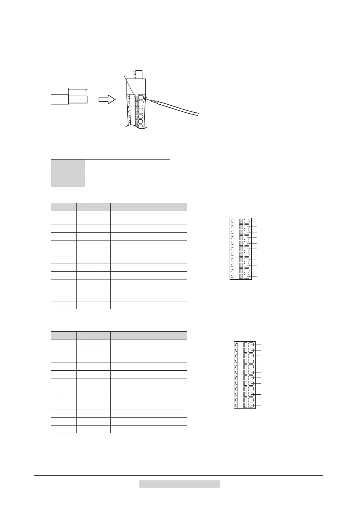
Connect the input signals to CN5 and the analog external input signals and output signals to CN7.
•
Applicable lead wire: AWG26 to 20 (0.14 to 0.5 mm
2
)
•
Lead wire strip length: 8 mm (0.31 in.)
Insert the lead wire while pushing
the button of the orange color with
a screwdriver.
8 mm
(0.31 in.)
Applicable crimp terminal
If crimp terminals are used, select the following terminals.
Manufacturer PHOENIX CONTACT GmbH & Co. KG
Model
A 0,25-7 [AWG24 (0.2 mm
2
)]
A 0,34-7 [AWG22 (0.3 mm
2
)]
A 0,5-8 [AWG20 (0.5 mm
2
)]
CN5 pin assignments
Pin No. Signal name Function
*
1
2
3
8
9
4
5
6
7
Manufacturer: PHOENIX CONTACT GmbH & Co. KG
Model: FK-MC0,5/11-ST-2,5
1 IN-COM0
Input signals common
(for external power supply)
2 IN0 Input terminal 0 [FWD]
3 IN1 Input terminal 1 [RVS]
4 IN2 Input terminal 2 [M0]
5 IN3 Input terminal 3 [M1]
6 IN4 Input terminal 4 [M2]
7 IN5 Input terminal 5 [FREE]
8 IN6 Input terminal 6 [STOP]
9 IN7 Input terminal 7 [ALM-RST]
10 IN8
Input terminal 8
[Not used (possible to assign)]
11 IN-COM1 0 V (for built-in power supply)
*
The signal in brackets [ ] is a function that is assigned at the time of shipment (speed control mode).
CN7 pin assignments
Pin No. Signal name Function
*
1
2
3
8
9
4
5
6
7
Manufacturer: PHOENIX CONTACT GmbH & Co. KG
Model: FK-MC0,5/12-ST-2,5
1 VH
Analog external setting input2 VM
3 VL
4 OUT0+ Output terminal 0+ [ALM]
5 OUT0– Output terminal 0– [ALM]
6 OUT1+ Output terminal 1+ [MOVE]
7 OUT1– Output terminal 1– [MOVE]
8 OUT2+ Output terminal 2+ [WNG]
9 OUT2– Output terminal 2– [WNG]
10 ASG Phase A output
11 BSG Phase B output
12 OUT-COM Common for ASG/BSG
*
The signal in brackets [ ] is a function that is assigned at the time of shipment (speed control mode).
 Loading...