Connection
−45−
2 Installation and connection
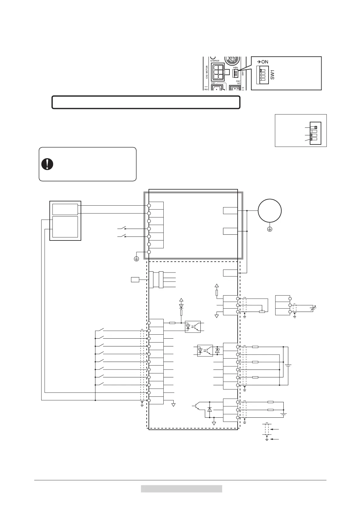
2.10 Connection diagram (example)
This section explains connection diagrams with the speed control mode (factory setting) as an example.
When using the built-in power supply, set the switch SW1-4
to the ON side. It is set to the OFF side (use an external power
supply) at the time of shipment. When using an external power
supply, use the switch with the factory setting as it is.
SW1-4
ON: Built-in power
supply is used
OFF: External power
supply is used
Speed control mode Sink logic: When using the built-in power supply
This is a connection example that the power supply is single-phase 100-120 VAC, the speed is
set using an analog external setting device to operate the motor with relays, switches and other
contact switches. The I/O signal in the brackets [ ] is the initial value.
Refer to p.99 for the assignment of I/O signals.
Setting of SW1
SW1-4: ON
Connecting the data setter
Connecting input signals
Speed setting by
PAVR-20KZ (sold separately)
or external DC voltage
Connecting output signals
R2∗3
R2∗3
3
L
Motor connector
Encoder connector
CN1
CN2
CN3
CN4
N
NC
NC
RG1
RG2
PE
2
3
4
5
6
7
1
2
Command
voltage
value
7
IN-COM0
CN5
CN6
CN7
CN7
CN7
IN0 [FWD]
IN1 [RVS]
IN3 [M1]
IN2 [M0]
VH
VM
VL
3
1
2
CN7
N.C.
VM
VL
IN4 [M2]
Shielded wire
0 V
+5 V
4
Main circuit
Control circuit
+5 V
PAVR-20KZ
External DC
voltage 10
or lower
6
9
8
10
12
11
5
10
8
9
11
1
IN5 [FREE]
IN6 [STOP]
IN7 [ALM-RST]
IN8∗1
IN-COM1
6.6 kΩ
ASG
BSG
OUT-COM
0 V
0 V
4.5 to 30.0 VDC
100 mA or less
4.5 to 30.0 VDC
20 mA or less
OUT0 [ALM]
OUT1 [MOVE]
OUT2 [WNG]
R1∗2
R1∗2
R1∗2
Connecting the
regeneration resistor
R
Normally
closed
150 °C
(302 °F)
Connecting the motor
Grounding the motor
Motor
Grounding the driver
Connecting
the power
supply
L
N
Circuit breaker
Electromagnetic
brake connector
*1
This is a connection when the TH input is assigned to IN8. The initial value is [Not used].
*2
Connect a current-limiting resistor R1 according to the power supply voltage used so that the current will not exceed 100 mA.
*3
Connect a current-limiting resistor R2 according to the power supply voltage used so that the current will not exceed 20 mA.
Connect the thermostat output of the
regeneration resistor to the terminal that
the TH input was assigned by changing the
“IN input function selection” parameter.
→
How to change: p.100

 Loading...