Made in the U.S.A.
TOOLING OPTIONS AND INSTALLATION
AVOID CRUSHING. Make sure all personnel are clear of the implement. Lower implement
to the ground, place tractor in park, turn off engine, and remove key.
USE BAR STANDS TO SUPPORT THE IMPLEMENT. Park implement on a clean, dry,
and level surface. An uneven surface could cause implement to shift or fall, resulting in
personal injury or death, as well as implement damage. Securely support all implement
components that must be raised. Remove buildup of grease, oil, or debris prior to
adjusting.
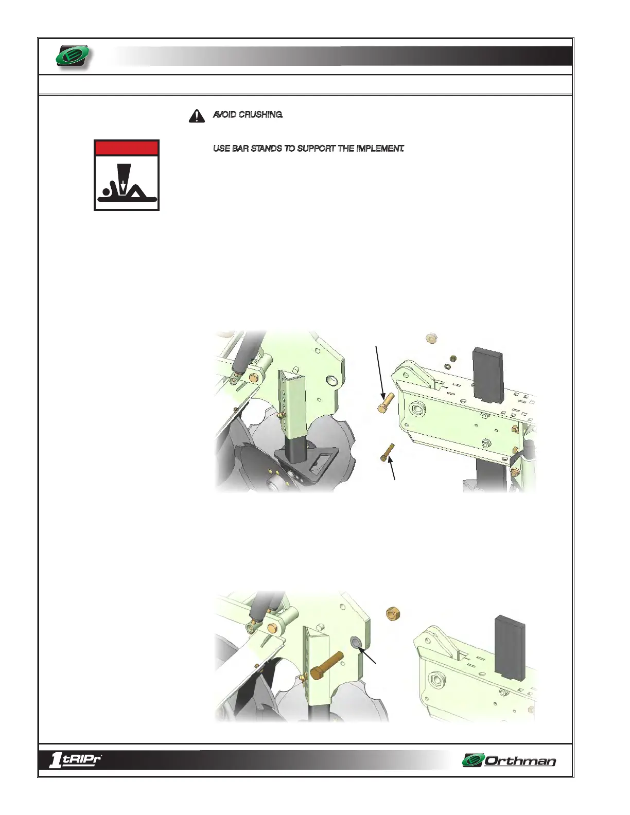
3. To install the main pivot bolt and crush sleeve, the tail section of the 1tRIPr® row unit
will have to be removed. Be sure to use a safe, adequate lifting device. It may be
easier to manipulate the tail section of the row unit with the tillage shank in a raised
position. It may also be desirable to have the 1tRIPr® machine lifted up with a tractor
so there is no pressure on the tail section of the row units. If not hooked to a tractor it
is important to only remove one row unit at a time and fully complete the installation
of one AR Linkage before starting on the next row unit, as the tail sections of the row
units keep the machine from tipping over backwards. To remove the tail section of the
1tRIPr® remove the ¾” x 3” long main frame bolt, and the ½” x 3” long shear bolt.
4. Once the tail section is removed, insert the main pivot crush sleeve into the main
frame. Then re-position tail section over the main frame and install main pivot bolt.
There is a hex collar on the side of the tail section to keep this bolt from rotating. Install
so the head of the bolt fits down inside this collar. Tighten the nut down and the tail
should clamp tight over the crush sleeve. It should be possible to lift the tail up as if it
were tripping and pivot it about this bolt now. See figures on page 4-11.
3/4” x 3” main frame
bolt
1/2” x 3”
Shear Bolt
Crush Sleeve
D A N G E R
4 - 10
 Loading...