Made in the U.S.A.
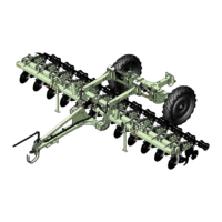
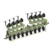
PREPARATION AND SETUP
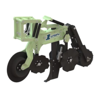
STANDARD ROW UNIT
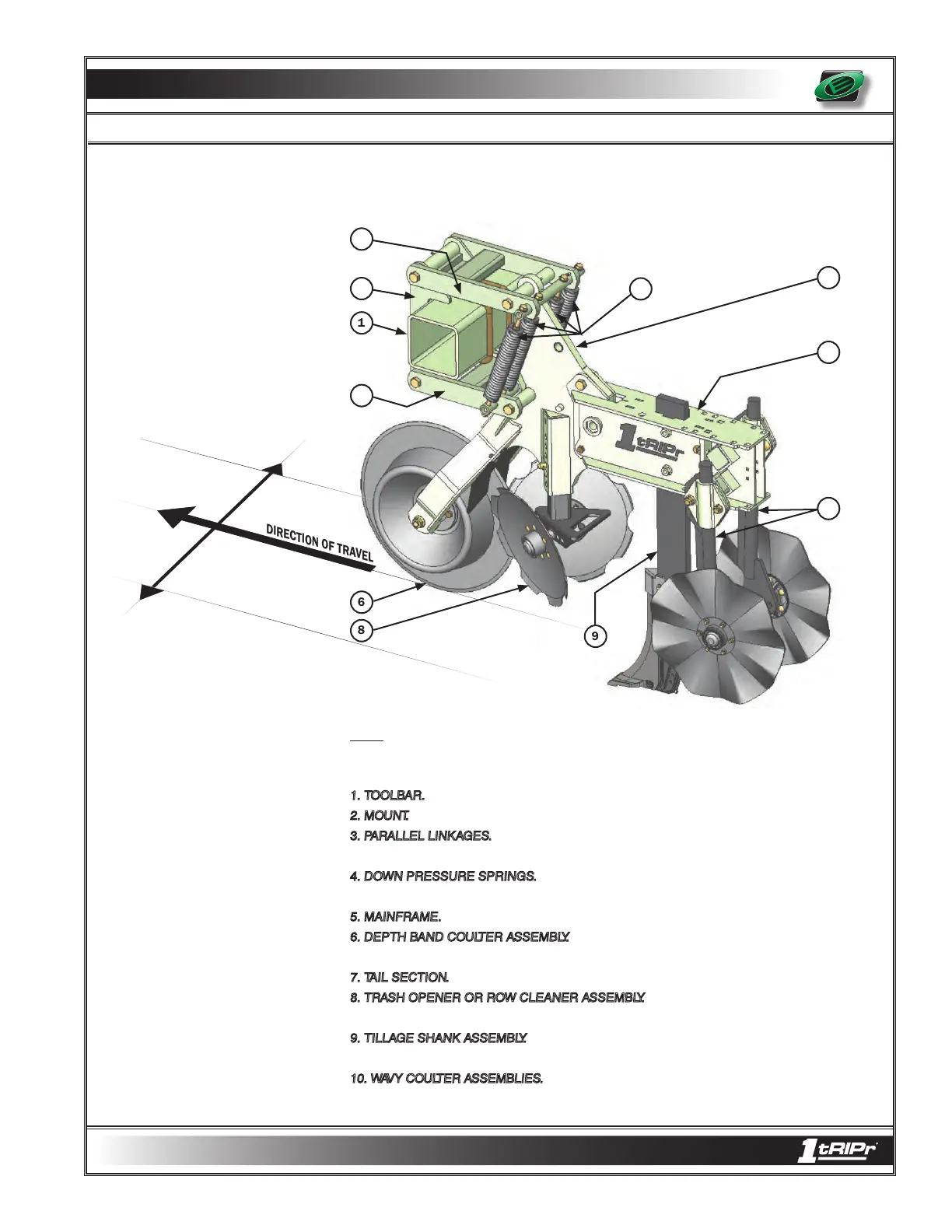
COMPONENT IDENTIFICATION
7
10
5
4
9
8
6
2
1
3
DIRECTION OF TRAVEL
RIGHT
LEFT
3
NOTE: Right and left as illustrated above and referenced from this point on, is determined
by facing the same direction the implement will travel while in use.
1. TOOLBAR.
Proven Orthman toolbar design provides unmatched strength.
2. MOUNT.
A wrap- around mount provides a long lasting row unit foundation.
3. PARALLEL LINKAGES.
Parallel linkages, with the ability to travel vertically, allow the row units
to operate independent of the toolbar to allow uniform tillage depth despite terrain variations.
4. DOWN PRESSURE SPRINGS.
Four adjustable down pressure springs per row unit
supply down pressure to assist with row unit tooling soil penetration.
5. MAINFRAME.
The row unit mainframe serves as the primary mount for row unit tooling.
6. DEPTH BAND COULTER ASSEMBLY.
The depth band provides consistent row unit tool-
ing depth while the coulter cuts surface and subsurface residue.
7. TAIL SECTION.
The tail section houses adjustable tooling.
8. TRASH OPENER OR ROW CLEANER ASSEMBLY.
The trash opener reduces field
residue directly behind the depth band coulter prior to the arrival of rearward tooling.
9. TILLAGE SHANK ASSEMBLY.
The tillage shank assembly
(mole shank or mole knife)
shatters
the root zone compacted layer, while allowing precision fertilizer placement at two depths, if desired.
10. WAVY COULTER ASSEMBLIES.
Wavy coulter assemblies provide “lift and pinch” action
to incorporate field residue, till, and firm the seedbed.
3 - 3