Made in the U.S.A.
FIELD SETTINGS
The AR Linkage comes set from the factory to trip easily, and will need adjusted to adapt
to your specific operating conditions. It is important that the user understand how the AR
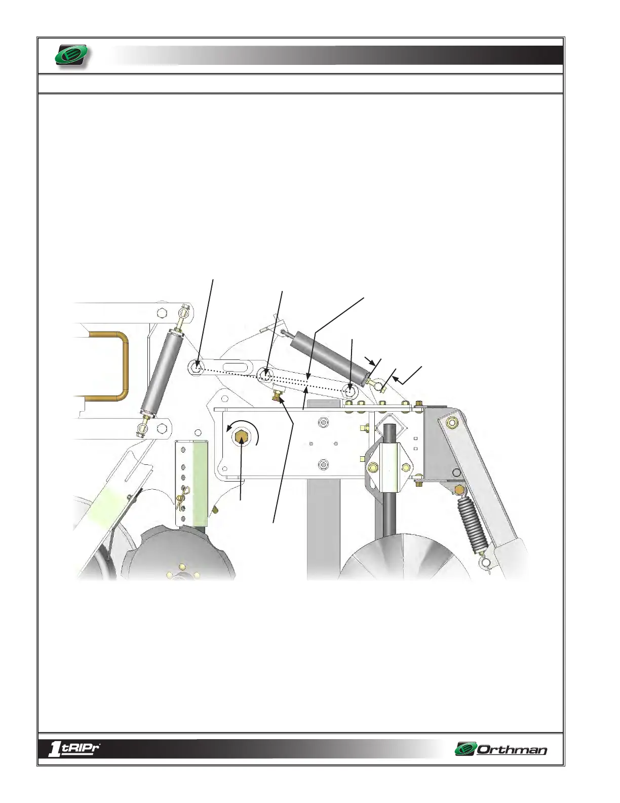
Linkage works and the results of the different adjustments. The image below identifies
the important geometry points and adjustment locations. Without the AR Linkage, the tail
would be free to rotate about point “D”. The Linkage installed keeps the tail from rotating
about point “D” by creating a brace between points “A” and “B”. That brace is made of two
links and has the ability to buckle in the middle at point “C”. When the shank encounters
an immovable object, the resulting force will buckle the linkage at point “C” allowing the
tail to rotate upward about point “D” until the obstacle is cleared. The upward rota-
tion of the tail, and the buckling of the linkage causes the four reset springs to become
stretched. The spring force stored in the stretched springs provides the power necessary
to rotate the tail downward, which in turn drives the shank back into the ground and snaps
the linkage back into place.
If you visualize a straight line between points “A” and point “B”, the distance point “C” is
away from that straight line directly effects how difficult it is to buckle the trip linkage.
The closer point “C” is to that line the more difficult it is to trip. The further away point “C”
is from that line the easier it is to trip. Our factory setting from Orthman Mfg. puts this
point “C” further from that line so it trips easily. Our factory setting (or distance “X” is ¾”)
Operators are encouraged to adjust this setting by loosening the jam nut under point “C”
and adjusting the set bolt. (with 15/16 wrenches) One full turn of this set bolt represents
about 1/8”. It may only be necessary to move the set bolt ¼ to ½ a turn to achieve the
correct offset distance for your soil and desired tripping operation.
Point A
Distance “X”
(Distance Point C is away from a
straight line from A to B)
Point B
Point C
Sprint tension
distance setting
“Y”
Adjustable
Screw for
setting “X”
Point
D
5 - 18