Made in the U.S.A.
FIELD SETTINGS
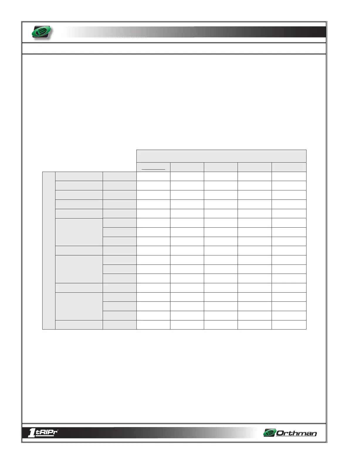
This table has been created to help understand the effects that the set screw setting
“X” and spring setting “Y” settings have on the AR Linkage’s ability to trip. The spring
settings across the top represent different options for spring setting “Y”. Coordinate
those with the numbers on the left of the chart that represent set screw setting “X”. The
numbers shown in the chart represent the estimated amount of force (in pounds) that
is required to trip the tail when the shank is at the deepest setting. For instance: With
the factory set screw setting of ¾”, and the factory spring setting of 2” it will take approx.
2,850 pounds of force at the foot piece of the shank at its lowest setting to trip the row
unit tail. As you can see, as the spring setting “Y” is decreased (tightened up), and as
the set screw setting “X” is decreased (unscrewed), the force required to trip is increased.
This will make it more difficult for the row unit to trip when it encounters an obstacle.
Orthman Manufacturing encourages the operator to start out at this factory setting, where
the row unit tail will most likely trip very easily. From that point you can adjust the set
screw and the reset springs to attain the AR linkage setting that works well for you.
The standard version of the 1tRIPr® without the AR linkage is equipped with a shear
bolt (pg. 5-11, 5-12). The amount of force it takes to shear this bolt is slightly over 8,000
lbs. Notice that the chart has values that exceed the 8,000 lb. mark. Orthman Manu-
facturing recommends using extreme caution when setting the AR Linkage to a setting
above 8,000 lbs. Using a setting that exceeds the 8,000 lb. mark is likely to increase the
chances of damaging the shank in the event an obstacle is encountered.
SPRING SETTING “Y”
factory 2” 1 7/8” 1 3/4” 1 5/8” 1 1/2”
SET SCREW SETTINGS “X”
factory setting 3/4 2863 3181 3340 3817 3817
1/4 of a turn out 23/32 3181 3340 3658 3897 3897
1/2 of a turn out 11/16 3260 3578 3817 3976 3976
3/4 of a turn etc. 21/32 3340 3658 3976 4056 4135
5/8 3578 3897 4135 4374 4612
19/32 3817 3976 4374 4612 4771
9/16 3976 4056 4612 4771 4851
17/32 3976 4374 4771 4851 5248
1/2 3976 4771 4930 5407 5567
15/32 3976 4851 5407 5567 5885
7/16 3976 4851 5567 5646 6759
13/32 3976 4851 5964 6362 7157
3/8 3976 4851 6759 6998 7634
11/32 3976 4851 6998 7793 7952
5/16 3976 4851 7555 8032 8747
9/32 3976 4851 7714 8747 9622
screw removed 1/4 3976 4851 7952 9702 10338
5 - 20
1 full turn out
2 full turns out
3 full turns out