Installation and Operation Manual of the EUROMATIK.net Page 12 (40)
Connecting remote switches
Two remote switches can be connected to the terminals 1, 2, 3 and 4.
These terminals are live and carry the mains voltage!
Opening the contact between the terminals 1 and 2 causes the filter pump, dosing
equipment and heater to be shut down immediately.
Closing the contact between the terminals 3 and 4 switches the filtration system on.
Additional input signals
Flow monitor
Instead of the jumper connected across the terminals 25 and 26 at the
factory, a flow rate monitor or a pressure monitor can be connected in order
to protect the pump additionally against dry running. Its contact must be
closed at the latest 10 seconds after the filter pump has started up, otherwise
the filter pump gets switched off and the fault indication lamp lights up. This
contact is not sensed in the backwashing mode of operation.
Pressure switch
A pressure switch that is installed in the pressure gauge connection of the
central valve can be connected to the terminals 27 and 28. The back-
flushing operation commences if the potential-free contact of the pressure
switch is closed for at least 10 seconds.
End position switch for the cover
A potential-free end position switch can be connected to the terminals 29 and 30, with which the system
switches to ECO mode automatically when the cover is closed.
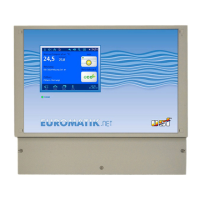
External touch-screen operating panel
An external touch-screen operating panel (Item no. 212.070.0520) can be connected
to the terminals 57, 58, 61 and 62. A 4-wire cable, 4 x 0.5 mm² (e.g. J-Y(St)Y 2 x 2 x
0.8, item no. 102.000.1012) with a maximum length of 50 m is used for this
connection.
Laying the connecting cable near power cables must be avoided in order to rule
out the possibility of interferences.
 Loading...