Installation and Operation Manual of the EUROMATIK.net Page 5 (40)
Installation
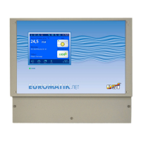
With the EUROMATIK.net you have purchased a high-class swimming pool controller. It is an accurate
and sensitive system that needs to be treated gently at all times. The membrane at the front should not
come into contact with chemicals. The controller is cleaned with a soft cloth and some water, if required.
At the time of installation, the regulations and provisions applicable at the place of installation must be
complied with.
Mounting
The housing is fixed vertically and permanently to a solid wall with adequate load-bearing capacity. The
place of installation must be dust-free and protected against water in order to ensure that the device works
properly. The ambient temperature should lie between 0° C and + 40° C and should be as constant as
possible. The relative humidity must not exceed 95% and no condensation may occur. Direct incidence of
heat or sunlight on the device must be avoided. The control unit and the external touch panel are not
suitable for outdoor installation.
Installation when using a swimming pool cover
The display of the EUROMATIK.net contains, among others, switches for operating the swimming pool
cover. These switches are inactive or off at the time of delivery. The switches can be activated or enabled
while the controller is being commissioned by selecting a swimming pool cover in the relevant menu. The
EUROMATIK.net with the switches for the swimming pool cover enabled should be installed only at
a place from where it is possible to have an unrestricted view of the entire swimming pool. The
switches meant for the "Swimming pool cover" should not be activated at locations from which
unrestricted view of the entire pool is not available! The emergency stop switch must be installed
on-site.
Electrical Connection
The control device must be fixed at a location where it is protected against moisture in accordance with its
class of protection. The power supply to the device must be fed via an all-pin main switch with contact
opening width of at least 3 mm and a residual current circuit breaker (RCCB) with I
FN
30 mA. When using
frequency inverters and pumps having speed control, the residual current circuit breakers specified for this
must be used and appropriate regulations must be observed and followed. Before opening the housing, it
is absolutely necessary to de-energize the device electrically. The electrical connection as well as
the work of adjustment and servicing should be carried out only by an approved electrician! The
connection diagrams enclosed and the relevant safety provisions applicable must be observed and
followed.
Low-voltage cables
Low-voltage cables should not be laid along with three-phase or AC cables in the same cable duct. In
general, laying low-voltage cables near three-phase or AC cables must be avoided.
Wiring diagrams
As the EUROMATIK may be combined with different types of filtration pumps, the connection of the pump
and the power supply has to be made according to the appropriate wiring diagram for the actually used
pump.
 Loading...