Operator's Manual
Issue 14 / Mar 2016
MercuryiPS
©2016 Oxford Instruments NanoScience. All rights reserved.
Page 16
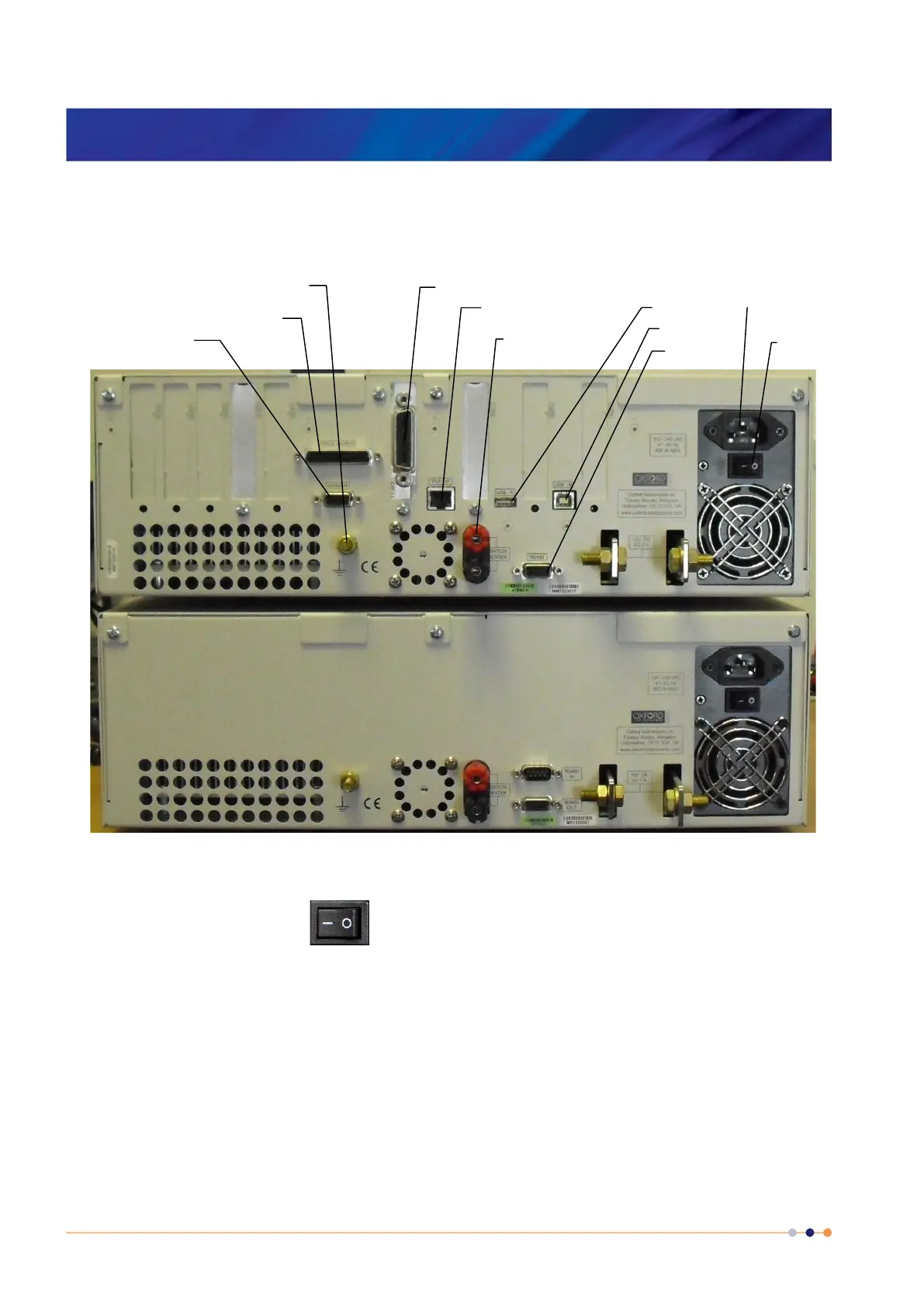
Figure 2 MercuryiPS rear panel (example)
The switch on the rear panel turns electrical power on and off. All connectors are
labelled.
2.2 Electrical power supply
The MercuryiPS automatically configures itself to match the supplied electrical power, as long
as the voltage and frequency are within the specified ranges. No user intervention is required.
The iPS powers all devices that are connected to it.
RS232 / ISObus
Main T sensor
connection
TCP/IP (Ethernet) USB-A
USB-B
Functional ground
Mains inlet
On/Off switch
Switch heater
output
GPIB (optional)
RS485


 To Next Page