Do you have a question about the Oxford Instruments NanoScience MercuryiPS and is the answer not in the manual?
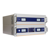
Power Supply for Superconducting Magnets.
Information on how to use the operator's handbook for installation, operation, and servicing.
Requirements for users to be trained on safe and effective operation of the equipment.
Defines the design purpose and operational limits of the MercuryiPS for superconducting magnet control.
States that misuse or incorrect operation may relieve Oxford Instruments of responsibility for damage or injury.
Details changes made to the manual across different revisions, including new features and corrections.
Provides details on contacting customer support and the necessary information to include for queries.
Outlines liability limitations, continuous improvement policy, and copyright terms for the document.
Lists and defines acronyms used throughout the manual for clarity and understanding.
Lists the standards and certifications the MercuryiPS power supply has been tested against.
Provides information about Oxford Instruments' specializations and their NanoScience division's capabilities.
Alerts users to essential precautions to ensure personal safety before operating the equipment.
Details the requirement for proper electrical grounding of the equipment and its components.
Warns of high voltages and specifies isolation procedures before maintenance or cover removal.
Emphasizes qualified personnel for maintenance and specifies safety steps before work.
Lists environmental restrictions, including avoiding flammable/explosive atmospheres and water ingress.
Advises using approved ESD procedures for equipment containing electrostatic sensitive devices.
Stresses the importance of maintaining adequate airflow by not obstructing ventilation spaces, especially in rack mounting.
Provides guidance on disposing of the lithium battery as solid waste according to regulations.
Describes the MercuryiPS as a high-precision power supply for superconducting magnets with various features.
Identifies the main features of the MercuryiPS front and rear panels, including controls and indicators.
Explains the automatic configuration of the MercuryiPS to match supplied electrical power within specified ranges.
Details how the MercuryiPS uses a measurement circuit to amplify, scale, and filter sensor voltage for digital conversion.
Lists the available interfaces (RS232, USB, Ethernet, GPIB) for connecting to a remote PC.
Provides a brief description of the internal components of the MercuryiPS.
Describes the chassis as a rugged steel construct designed for rack mounting with integrated cooling fans.
Details the off-the-shelf switch-mode power supply used, its specifications, and control.
Explains the touch-screen interface, its display, and the ambient-light sensor for brightness adjustment.
Describes the motherboard's role and details the eight expansion slots for daughter boards.
Describes the pressure board for measuring pressure transducer signals and controlling pressure in cryogenic systems.
Illustrates the layout of expansion slots and specifies allowed and typical positions for daughter boards.
Explains the magnet control board's function in regulating output current and controlling the persistence switch heater.
Describes the filter board as the final stage filter for the main current output and its role with the Modbus port.
Details the bank of power resistors used for dissipating stored energy during magnet run-down.
Explains how the MercuryiPS identifies faults, uses a buzzer for errors, and employs interlocks for safety.
Instructs users to check the supply voltage is within the specified range to avoid permanent damage.
Details how to mount the equipment in a rack or on a bench, ensuring rear access for connections.
Specifies the requirement not to position the iPS in a background magnetic field exceeding 25 gauss to avoid erratic behavior.
Advises using only the supplied mains cable and meeting electrical supply requirements for different regions.
Provides step-by-step instructions for powering up the MercuryiPS for the first time and its initialisation.
Introduces the touch screen as the graphical user interface (GUI) for operating the MercuryiPS.
Describes the features of the standard magnet home screen, including status panels and control buttons.
Explains the function of magnet control buttons like Hold, To Set, To Zero, and Heater ON/OFF.
Describes the button that indicates the status of the selected interface and allows connection/disconnection.
Explains that custom home pages are factory-configured and cannot be re-configured by the user.
Describes the information displayed in typical channel-summary widgets on the home page.
Explains how to use drop-down menus indicated by a downwards-pointing arrow for selecting options.
Describes how to use scroll buttons to reveal more menu items or information when space is limited.
Explains the use of soft keypads for entering alphanumeric or numeric data into parameter boxes.
Details the operation of the numeric keypad for entering numbers, including deletion and saving.
Explains the operation of the alphanumeric keypad for entering text, including character selection and case change.
Describes how to use up and down arrows to adjust integer values in numeric parameter boxes.
Explains how button labels change to reflect the current state or function of the iPS.
Identifies common buttons like Home, Load, Save, Apply, and Cancel that appear on multiple GUI pages.
Provides a step-by-step guide on how to set the system's date and time using the touch screen interface.
Introduces the capability to monitor up to six signals as a function of time using the touch screen.
Explains how to use the Plot Configuration page to select which signals are plotted and view real-time traces.
Details how to select signals from available boards or a single board to be added to the plot.
Describes how to adjust the scaling of a plot by zooming in/out and panning using touch gestures.
Explains the principles of superconducting magnets with persistence switches and their configuration with the IPS.
Describes a quench event in magnet operation, its effects, and how the power supply responds.
Details how voltage transients exceeding limits trigger quench mode and the PSU's response.
Explains the 'Slaves Detected' value, representing the number of iPS-S units detected during boot.
Describes the 'Magnet Type' setting (Solenoid, Split Pair, Vector Rotate) and its impact on the configuration table.
Explains the 'Config' parameter that defines the power supply units' configuration in the control loop architecture.
Details how the 'Config' parameter defines units as parallel or series for different magnet types and power supply configurations.
Guides on allocating Mercury units to configuration groups for parallel or series setups via the 'Eng Config' table.
Defines the current limit for a group of power supply units and its impact on ramping.
Defines the voltage limit for a group and its role in detecting QUENCH mode.
Explains the current-to-field ratio parameter used for displaying equivalent applied field in Tesla.
Describes the self-inductance value of the magnet used for damping factors in current drive control loops.
Details the 'Transient Time' parameter used for QUENCH detection to prevent false trips.
Specifies which unit in a group is used for the switch heater drive output.
Defines the switch heater current required to open the switch.
Explains the 'Bipolar' and 'Unipolar' modes for power supply group ramping direction.
Details parameters for specifying safety thresholds (None, Temperature, Helium level, External signal) to inhibit operation.
Sets the temperature threshold below which it is safe to run the magnet.
Sets the level threshold above which it is safe to run the magnet.
Switches the Intelligent Switch function ON/OFF, managing switch heater power dissipation.
Provides an estimate of the switch heater resistance.
Estimates the switch superconducting element resistance in its normal state.
Estimates the total resistance of the main current leads.
Defines the time for the switch to OPEN after the switch heater is turned ON.
Defines the time for the switch to CLOSE after the switch heater is turned OFF.
Controls the 'Catch' routine designed to catch the magnet if the switch breaks open during persistence setting.
Defines a band around the target current for 'fine trim' mode at the end of a magnet ramp task.
Details how to energise the superconducting magnet by entering set points and ramp rates via the home screen.
Explains pre-programmed ramp rate limits to prevent rapid ramping or excessive current dumping in the switch.
Lists and defines the four types of rate limits: LRMZ, LRMF, MRFa, and MRSl.
Shows an example of how magnet rate limits are applied and how the 'Rate Limit' indicator functions.
Explains the Fast/Slow rate setting on the 'Set Point / Set Rate' page and when to use slow rates.
Details how to add or remove rows from the rate limit table and edit values within it.
Refers to section 4.1 for quench event description and how the Mercury handles it.
Explains how to configure the iPS for controlling up to 3 independent axes using 'Vector Rotate' mode.
Describes the Vector Rotate mode home screen with panels for X, Y, and Z axes and accessing axis-dependent settings.
Introduces temperature measurement capabilities, supported sensor types, and topics covered in the chapter.
Details the connection of temperature sensors via the 9-way D-connector on the rear panel.
Explains how to connect thermocouples using correct wire types and how biasing improves measurement stability.
Guides on configuring widgets on the home page to display temperature sensor readings.
Details how to set sensor type, calibration files, and other parameters in the Sensor Details page.
Lists the typical sensor readings displayed, such as excitation current, power, resistance, temperature, and voltage.
Explains how to select the sensor type (thermocouple, PTC, NTC, Diode) from a drop-down menu.
Guides on selecting calibration files and understanding interpolation methods for sensor readings.
Instructions on how to clear a configured widget on the home page and reset it to default.
Explains how to use generic calibration files and adjust scale/offset for specific sensors like PTC and NTC.
Details the process of adjusting a generic calibration file using known temperature points (T1 and T2) for accurate sensor readings.
Describes different types of temperature sensors supported, including thermocouples and resistance thermometers.
Explains the principle of thermocouples, their voltage source behavior, and cold-junction compensation.
Describes metallic resistance thermometers (PTC), their resistance-temperature relationship, and measurement method.
Explains semiconductor resistance thermometers (NTC), their resistance-temperature relationship, and measurement method.
Describes semiconductor diodes and how the iPS measures their voltage to determine temperature.
Details the excitation current modes (Unipolar, Bipolar, Soft edge) for resistance and diode sensors.
Explains how calibration tables are used for different sensor types, their format, and interpolation.
Lists available generic calibration files for various sensor types and their temperature ranges.
Provides further information on thermocouple principles, including thermoelectric emf and potential errors.
Shows an example of configuring a home page widget for a Au-Fe/chromel thermocouple with liquid nitrogen reference.
Discusses the use of internal or external reference junctions for thermocouple measurements and accuracy limitations.
Recommends external reference junctions for high-accuracy thermometry, especially at low temperatures.
Introduces the level-meter board for measuring cryogen levels (Helium, Nitrogen) and raising errors if levels are low.
Explains the operating principles of the level-meter board, differentiating between helium and nitrogen probes.
Describes the operation of the nitrogen-level probe, which uses concentric steel tubes as a capacitor.
Explains the reasons for using different measurement methods for liquid helium and liquid nitrogen.
Provides instructions for installing the level-meter board, starting with removing the top cover.
Details the process of fitting the level-meter daughter board into an expansion slot, including removing blanking plates.
Emphasizes the importance of correctly tightening the daughter board retaining screw for low-impedance connection and EMC compliance.
Outlines steps to verify the level-meter board is detected and can be operated in Local mode.
Lists the pin connections for the 9-way D-connectors for both Helium and Nitrogen probes.
Guides on configuring a widget to display Helium level, setting resistance values for 0% and 100% levels, and pulse parameters.
Guides on configuring a widget for Nitrogen level, recording frequencies for 0% and 100% levels, and setting pulse counting period.
Describes the General settings page, including Home Screen Revert Option and Remote Lock parameters.
Explains Remote Access settings and the choice between SCPI and Legacy command sets for remote control.
Details how to find the Application version number and the Cryosys application refresh rate.
Describes the Display settings page for configuring brightness, auto-dim, timeout, and style.
Explains how to view fitted boards in expansion slots, showing details like ID, Type, Serial No., and Board Rev.
Guides on setting the MercuryiPS internal clock (Time and Date) using the touch screen interface.
Explains how to load calibration files from a USB memory stick using the File Transfer page.
Details the procedure for updating the Mercury application and board firmware using a USB memory stick.
Explains how to enter ENGINEERING mode to access advanced features and change system parameters with caution.
Allows saving and restoring system configurations, including the original factory configuration.
Describes the interface for saving files, such as PID files, by entering a filename and tapping Save.
Introduces remote operation capabilities via RS232, ISOBUS, GPIB, Ethernet, and USB interfaces.
Explains how to configure RS232 and ISOBUS settings, including address, baud rate, data bits, parity, and stop bits.
Details the pin assignments for RS232 serial connections and voltage levels for transmitted/received data.
Guides on configuring the GPIB address, noting the primary and secondary address settings for SCPI and Legacy commands.
Provides GPIB connection requirements and a warning about cable disconnection while instruments are powered up.
Explains Ethernet configuration, including IP address, subnet, gateway, and DHCP settings.
Details USB configuration, cabling requirements, and where to download necessary USB drivers.
Provides instructions on switching control between local (GUI) and remote operation modes via the General settings.
Explains the conventions used for listing SCPI commands, including keywords, parameters, and alternative values.
Describes the SCPI and legacy command sets supported by the iPS and provides recommendations for their use.
Introduces SCPI commands, their structure, and examples of supported commands like clearing status and reading identity.
Explains SCPI command protocols, including case sensitivity, keyword length, and command line termination.
Shows the command to read the instrument identity and the expected format of the reply.
Defines the basic structure of SCPI commands, including verbs, nouns, and handling of invalid commands.
Explains the two verbs (READ, SET) that the interface controller can issue and how the iPS replies.
Describes the hierarchical structure of nouns used in commands to address units, devices, and signals.
Lists system commands for setting level, time, date, user access, and other system-level parameters.
Explains how to address a magnet power supply device using its UID and the command structure.
Details how to address a temperature sensor using its UID and the command structure.
Provides an example command for configuring a temperature sensor and the expected response.
Explains how to address a level meter sensor using its UID and the command structure.
Details how to address an auxiliary I/O daughter board using its UID and the command structure.
Explains how to address a pressure sensor using its UID and the command structure.
Lists possible responses when an invalid command is sent, with reasons for each response.
Introduces legacy commands used in previous models, their protocols, and monitor commands.
Explains the case sensitivity and format of legacy commands.
Details legacy monitor commands like Rn (Read Parameter) and V (Read Version).
Explains the EXAMINE command for reading the iPS status and the format of the returned string.
Lists legacy control commands such as ACTIVITY, Set Switch Heater State, Set Target Current, and Set Target Field.
Provides an overview of the temperature sensor board, supported sensor types, and reading rates.
Details how to fit a temperature sensor board, including slot placement recommendations.
Outlines steps to verify the temperature sensor board is detected and functional after installation.
Explains the circuit configuration for measuring resistance or voltage, depending on the sensor type.
Describes the voltage measurement mode used with diode sensors or thermocouples, including a block diagram.
Explains the constant current mode for PTC sensors, detailing the circuit configuration and measurement technique.
Describes the constant voltage mode for NTC sensors, detailing the circuit configuration and measurement technique.
Explains the ratiometric calibration process for the temperature measurement circuit, including autocalibration.
Details the functions of the auxiliary I/O board, including stepper motor drive, digital I/O, and PWM signals.
Lists the optional auxiliary board's capabilities, such as driving stepper motors and providing digital inputs/outputs.
Explains how the auxiliary board controls motorised needle-valves for gas-flow regulation in cryostats.
Provides instructions for installing an auxiliary I/O board into an expansion slot.
Lists the pin connections for the 15-way D connector and 2-way miniature connector on the auxiliary I/O board.
Guides on configuring a home page widget for an input on the auxiliary I/O board, including nickname and type selection.
Guides on configuring a home page widget for an output on the auxiliary I/O board, including nickname and type selection.
Describes the pressure board for isolated, precision pressure measurements from transducers.
Explains the pressure board's circuit, powered by 12V, using a DC-DC converter and microcontrollers for measurements.
Provides instructions for installing a pressure board into an expansion slot.
Outlines steps to verify the pressure board is detected and functional after installation.
Lists the pin connections for the 9-way D connector on the pressure board.
Guides on configuring a widget for a pressure sensor input, selecting the device, signal, and saving changes.
Details how to set sensor type, calibration files, and excitation parameters for pressure sensors.
Describes the GPIB daughter board as a parallel interface for controlling multiple instruments independently.
Details how to fit a GPIB board into the dedicated GPIB expansion slot.
Provides GPIB connection requirements and a warning about cable disconnection while powered.
Provides instructions for cleaning the sensitive touch-screen using recommended products and a soft cloth.
Explains how to calibrate the internal electronics of each temperature sensor circuit via the Sensor Details page.
Advises lubricating the fan every couple of years with a water-displacing aerosol lubricant.
States that the lithium-ion coin-cell on the motherboard may need replacement and requires trained personnel.
Explains how the iPS identifies errors, triggers audible alarms, and uses interlocks for safety reasons.
Describes the Current and Historic Alarm Logs pages for recording and reviewing alarm events and their correction.
Lists simple steps for clearing software/firmware alarms, such as restarting or updating firmware.
Describes common external faults due to wiring and the need for a DVM for diagnosis.
Provides a comprehensive list of alarms, associated interlocks, and recommended actions to resolve them.
Lists the physical dimensions (width, depth, height) and weight of the MercuryiPS unit.
Details the electrical specifications, including mains supply voltage, frequency, power, and compliance standards.
Lists specifications for magnet outputs, including current range, resolution, stability, drift, accuracy, and ripple.
Details specifications for sensor inputs, including supported types, resistance ranges, excitation modes, and ADC resolution.
Lists the specifications for PC interfaces, including serial, USB, GPIB, and Ethernet.
Specifies the electrical isolation ratings between different terminals and chassis for safety.
Lists environmental conditions for operation, shipping, and storage, including temperature, pressure, and humidity.
Provides specifications for the Helium and Nitrogen probe functions of the level meter board.
Details specifications for the pressure board, including measurement accuracy, resolution, and ranges.
Provides contact information for Oxford Instruments customer support offices worldwide.
| Brand | Oxford Instruments |
|---|---|
| Model | NanoScience MercuryiPS |
| Category | Power Supply |
| Language | English |