Operator's Manual
Issue 14 / Mar 2016
MercuryiPS
©2016 Oxford Instruments NanoScience. All rights reserved.
Page 54
To execute the ramp tap “Hold” on the Home screen to unclamp the power supply outputs and
to start the PWM output stages. You will hear some clunking as the crow-bar relay(s) open.
If the magnet is fitted with a switch, tap the “Heater” button to turn on the switch heater. Wait for
the heat switch to activate to be sure it is open. Now tap “To Set” to start the ramp to the output
at the pre-entered set point at the pre-entered set rate.
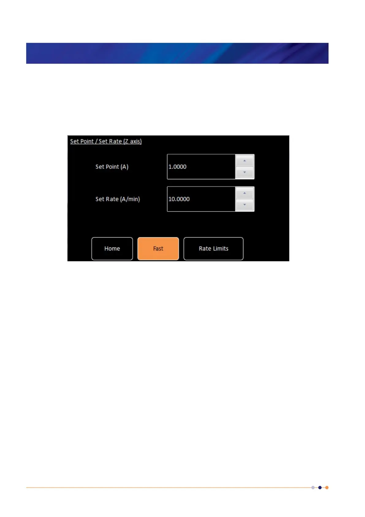
Figure 14. Set Point / Set Rate screen
The Mercury iPS-M will distribute the set points and set rates to each unit in the group
configuration. So, for example, if the group were a 180-10 which would be a parallel group of
1 x iPS-M plus 2 x iPS-S’s and if a set point of 150A were entered the target currents would be
distributed as 50A for each of the 3 parallel units (iPS-M, iPS-S
1
and iPS-S
2
). Similarly if a set
rate of 9A/minute were entered, the target rates would be distributed as 3A/min for each of the 3
parallel units (iPS-M, iPS-S
1
and iPS-S
2
). When “To Set” is tapped, each unit starts it’s own
controlled ramp to achieve the group requirement of 150A at 9A/min.
At the end of the ramp the units drop back into “Hold” mode. In this mode there is a fine trim
function running which ensures the output is held constantly and precisely at the set point.
5.1 Rate Limits
As an additional form of operational protection for the magnet, the power supply can be pre-
programmed with sets of ramp rate limits to avoid ramping the magnet too quickly or dumping
current in the switch too quickly. There are 4 types of rate limit:-
 Loading...