Digital Video Recorder
5
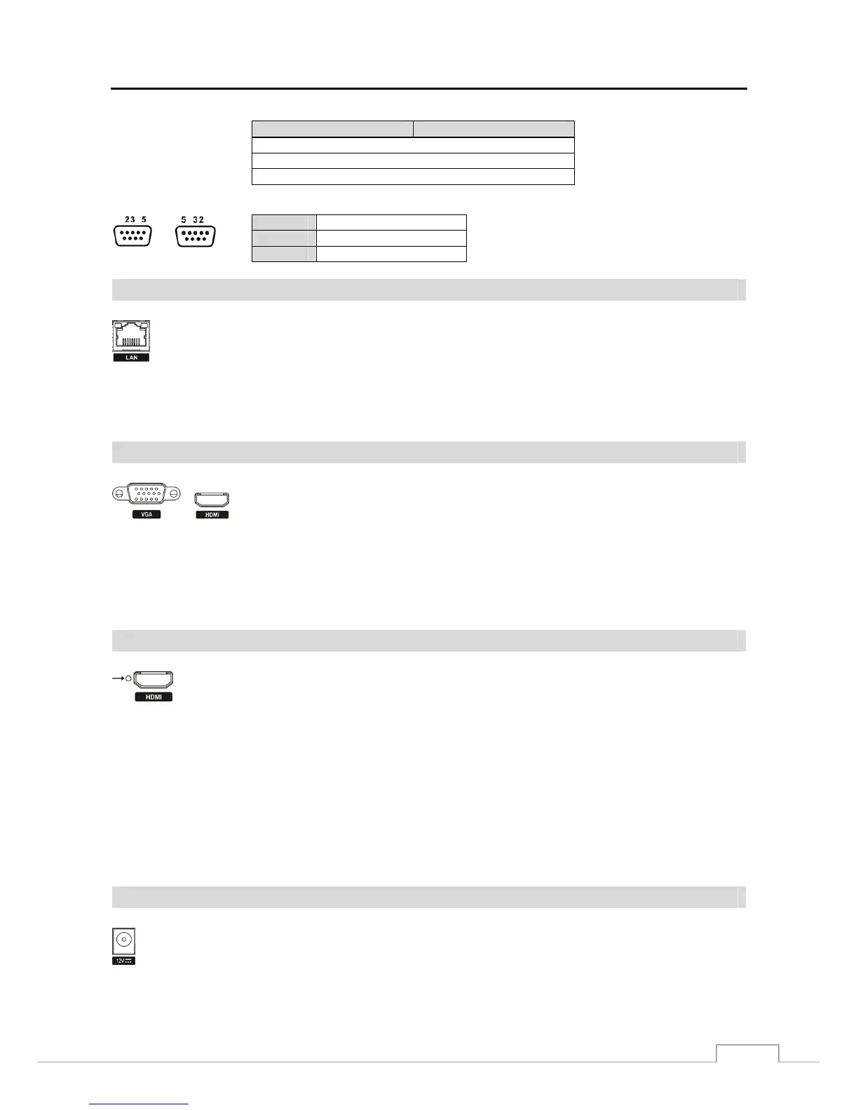
Connector Pin Outs:
Master Unit Slave Unit
RX → To → TXD
TX → To → RXD
GND → To → GND
NOTE: Refer to the following for pin-out details for the 9-pin connector of the slave unit.
Male
Female
Pin 2
RXD (Receive Data)
Pin 3
TXD (Transmit Data)
Pin 5
GND (Ground)
Network Port
CAUTION: The network connector is not designed to be connected directly with cable or wire
intended for outdoor use.
Video Out
A VGA connector is provided so that you can use a standard, multi-sync computer monitor
as your main monitor. Use the cable supplied with your monitor to connect it to the DVR.
An HDMI (High-Definition Multimedia Interface) connector is provided so that you can
use an HDMI monitor as your main monitor.
NOTE: Connect the monitor before the DVR boots so that video can be displayed on the monitor with the resolution
you have set during system setup. If you want to use both the HDMI and VGA Monitor connectors, one
of the monitors should be connected before the DVR boots, and the other monitor should be connected
after the DVR boots.
Factory Reset Switch
The DVR has a Factory Reset switch to the left of the HDMI connector on the rear panel. This
switch will only be used on the rare occasions that you want to return all the settings to the original
factory settings.
CAUTION: When using the Factory Reset, you will lose any settings you have saved.
To reset the unit, you will need a straightened paperclip:
1. Turn the DVR off.
2. Turn it on again.
3. While the DVR is initializing, the front panel LEDs will blink. When the front panel LEDs blink, poke the
straightened paperclip into the unlabeled hole to the left of the HDMI connector.
4. Hold the reset switch until the DVR’s internal buzzer sounds twice.
5. Release the reset switch. All of the DVR’s settings are now at the original settings it had when it left the factory.
Power Cord Connector
The DVR can be networked using the 10Mb/100Mb/1Gb Ethernet connector. Connect a Cat5 cable
with an RJ-45 jack to the DVR connector. The DVR can be networked with a computer for remote
monitoring, searching, configuration and software upgrades. See Chapter 3 ─ Configuration for
configuring the Ethernet connections.
Connect the connector from the adaptor to the DVR, and connect the AC power cord to the adaptor and
then to the wall outlet.