45 (E)
5. External device control interfaces
5-1. LAN connection
Use LAN cables to connect the AW-HE50, AW-RP50 and host computer.
When connecting the unit directly to another device, use a crossover cable.
For network connections via a device such as a hub (switching hub), use straight cables.
When a hub is not going to be used, ensure that the length of the LAN cable does not exceed 100 meters (when a cable of
category 5 or above is used).
For further details on the AW-HE50 and AW-RP50 connections and settings, refer to “2-2-2. Example of connections”
(<Basics> Operating Instructions).
For details on the functions available when connection has been made to the host computer, refer to “6. Connections with a
computer”.
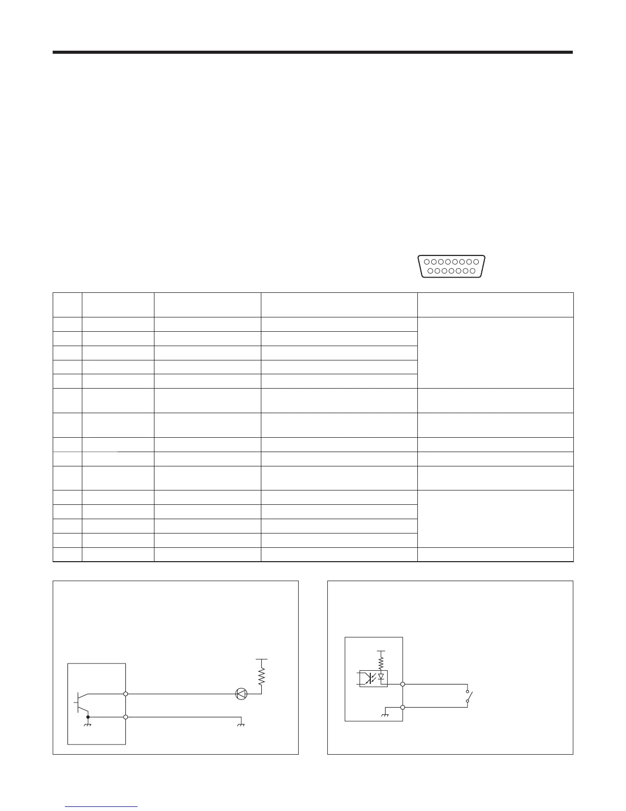
5-2. TALLY/GPI
The TALLY/GPI connector features five contact input ports
for controlling the unit from an external device and seven
open collector output ports for outputting the tally and status
information from the unit to an external device.
(D-sub 15-pin, female, inch thread)
81
15
9
Pin
No.
Signal Input/output Details of signal Operation
1 TALLY OUT1 Open collector output Tally output of input image 1 A low-level signal is output during tally
output.
2 TALLY OUT2 Open collector output Tally output of input image 2
3 TALLY OUT3 Open collector output Tally output of input image 3
4 TALLY OUT4 Open collector output Tally output of input image 4
5 TALLY OUT5 Open collector output Tally output of input image 5
6 ALARM Open collector output Fan alarm or power alarm output A low-level signal is output when trouble
has occurred.
7 KEY ON Open collector output Key combination status output A low level is output during key
combinations.
8 (RESERVE) Contact input (Reserve)
9 NC Not used
10 Tally Disable Contact input Tally signal enable/disable This signal is enabled by the contact
input (and disabled when open).
11 AUTO Contact input AUTO button of transition part The signal is made operational by the
contact input (30 ms or more).
12 CUT Contact input CUT button of transition part
13 KeyON Contact input KEY ON button of transition part
14 PinPON Contact input PinP button of transition part
15 GND Ground Ground
GND
TALLY OUT1 – 5
ALARM
KEY ON
Tally LED
Example of an open collector output connection
Ensure that the conditions given below are satisfied.
Dielectric strength: Max. DC 24 V
Current: Max. 50 mA
AW-HS50
(Max. voltage: 24 V)
(Max. current: 50 mA)
GND
Tally Disable
AUTO
CUT
KeyON
PinPON
+3.3 V
Example of a contact input connection
Provide contact inputs.
AW-HS50
 Loading...