High-Speed Counter and Pulse Output
FPΣ User's Manual
124
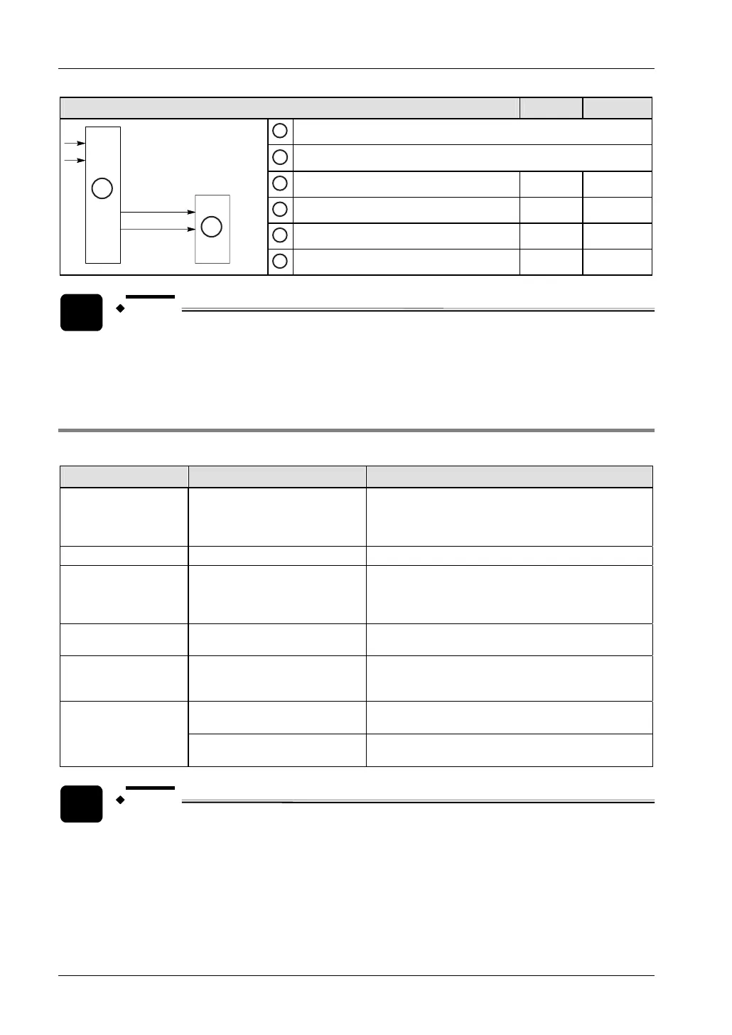
Using channel 0 2
A
PLC
B
Motor driver
1
Home input X2 X5
2
Near home input (see note) e.g. X3 e.g. X6
3
Pulse output Y0 Y3
A
B
4
Direction output Y1 Y4
NOTE
Any input that is not used for other applications can be used as the near home
input.
7.4.3 Instructions and system variables
Use the following instructions to perform various positioning tasks:
Type of control Instruction Description
Trapezoidal control F171_PulseOutput_Trapezoidal
Provides trapezoidal (table-shaped) control for
automatically obtaining pulse outputs. The initial
speed, target speed, acceleration/deceleration time,
and target value need to be specified.
Home return
F171_PulseOutput_Home Permits automatic home return operation.
JOG operation
F172_PulseOutput_Jog
Causes pulses to be output as long as the execution
condition is TRUE. A target value can also be set, so
that pulse output stops when the target value is
matched.
Data table control F174_PulseOutput_DataTable
Permits positioning control in accordance with the
specified parameters.
Linear interpolation
control
F175_PulseOutput_Linear
Causes pulses to be output using linear interpolation
control. Composite speed, acceleration/deceleration
time, and target value need to be specified.
F176_PulseOutput_Center
Causes pulses to be output using circular interpolation
control. The center position needs to be specified.
Circular interpolation
control
F176_PulseOutput_Pass
Causes pulses to be output using circular interpolation
control. The pass position needs to be specified.
NOTE
When using the pulse output instructions F171_PulseOutput_Trapezoidal,
F171_PulseOutput_Home, F172_PulseOutput_Jog, F174_PulseOutput_DataTable,
F175_PulseOutput_Linear, specify an initial frequency of 30kHz or less.
Otherwise, the first pulse may be lost.
Counter and pulse output settings as well as elapsed values are stored in special data
registers. The pulse output status is stored in special internal relays. To access special data