Communication
FPΣ User's Manual
184
8.5.6.1 Wiring
With 1:N communication, the various RS485 devices are connected using twisted pair cables.
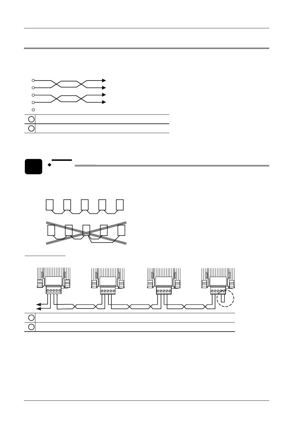
Connection diagram for FPG-COM3
E
+
-
+
-
1
2
1
Transmission line 1 to external device with RS485 port
2
Transmission line 2 to external device with RS485 port
The (+) terminals as well as the (-) signals of the two transmission lines are connected
internally, and either terminal pair is assigned to COM port 1.
NOTE
Wiring should extend from one station to the next. Never run two wires from a
single station to two other stations.
Correct:
Incorrect:
Bus termination
FPΣ FPΣ FPΣ FPΣ
1
To converter for RS232C connection of computer
2
Transmission line
Bridge the E terminal and the free (-) terminal on the first and on the last station of the
transmission line to terminate the data bus. (See "
FPG-COM3: 1-Channel RS485 Type" on
page
160.)